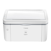
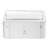
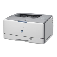
Do you have a question about the Canon LBP3300 Series and is the answer not in the manual?
Provides a comprehensive list of technical specifications for the printer model.
Explains the hazards of laser light and protective measures for safe operation.
Instructs on proper handling of the laser scanner unit to prevent damage and ensure safety.
Displays safety warnings regarding invisible laser radiation when the unit is open.
Explains the laser system, including its components and operational principles.
Details the laser/scanner unit, its components, and the twin beam method.
Describes the circuit responsible for controlling the laser diodes based on engine controller signals.
Provides an overview of the image formation system components and their roles.
Details the image formation process involving photosensitive drum, laser, toner, and transfer.
Breaks down the print process into 5 blocks and 7 steps for clarity.
Explains the two steps involved in forming an electrostatic latent image on the photosensitive drum.
Explains primary charging of the drum and laser beam exposure for latent image formation.
Details the development process where toner makes the latent image visible on the drum.
Explains the development cylinder, toner projection, and bias control for image density.
Describes the transfer process where toner is moved from the drum to the print paper.
Explains paper separation from the drum and the fixing process using heat and pressure.
Explains the system responsible for picking up and feeding paper through the printer.
Provides an overview of the pickup and feeding system, including feed rollers and sensors.
Details the pickup/feed system, paper paths, sensors, and jam detection logic.
Explains the various types of paper jams and how the printer detects them.
Provides an overview of the paper sensors and the CPU's role in detecting jams.
Describes various delay and stationary jams and their detection criteria.
Covers other jam types like wrapping, start-up residual, and door open jams.
Describes the printer's power supply system, including low-voltage conversion.
Details the low-voltage power supply circuit that converts AC input to DC voltages.
Provides a block diagram of the power supply circuit, showing components and connections.
Explains the protective functions of the low-voltage power supply circuit to prevent failures.
Details the overcurrent protective function and fuse protection within the power supply circuit.
Explains the fixing unit's function in fusing toner and the delivery system for outputting prints.
Provides an overview of the fixing and delivery units, including heater, thermistor, and thermoswitch.
Details the structure and operation of the fixing unit, including the on-demand fixing method.
Explains the fixing temperature control system, including its modes and target temperatures.
Details the four modes of fixing heater temperature control: initial, normal, between-sheets, and down-sequence.
Describes the three protective functions to prevent abnormal temperature rise of the fixing heater.
Outlines conditions under which the CPU determines a fixing unit failure.
Lists error codes, their major causes, and recommended remedies.
| Print Technology | Laser |
|---|---|
| Print Resolution | 600 x 600 dpi |
| Paper Capacity | 250 sheets |
| Duplex Printing | Manual |
| Connectivity | USB 2.0 |
| Printer Type | Monochrome Laser Printer |
| First Print Out Time | 9 seconds |
| Supported Paper Sizes | A4, A5, B5, Legal, Letter, Executive, Envelope (DL, COM10) |
| Memory | 8 MB |
| Operating System Compatibility | Windows, Mac OS, Linux |
| Print Speed | 21 ppm |
| Print Speed (A4) | Up to 21 ppm |
