8 9
Model No. 088-0798-4
ASSEMBLY ASSEMBLY
ASSEMBLY ASSEMBLY
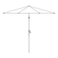
Step 2
Requires A, B, C, D, F, G, H, I, S, T, V
1. Attach the bottom part of the foot plate support arm (F) to the 360°
rotating unit (D), use M6x10mm bolt (I) and hex wrench S5 (T) to
secure.
2. Line up the bolt holes on the 360° rotating unit (D) with the
corresponding bolt hole on the two brackets (A & B), use M10x25 mm
bolt (G), M10 washer (H) and hex wrench S8 (S) to secure.
3. Attach the base tube (C) to the 360° rotating unit (D), use M10x20
mm bolt (V), M10 washer (H) and hex wrench S8 (S) to secure.
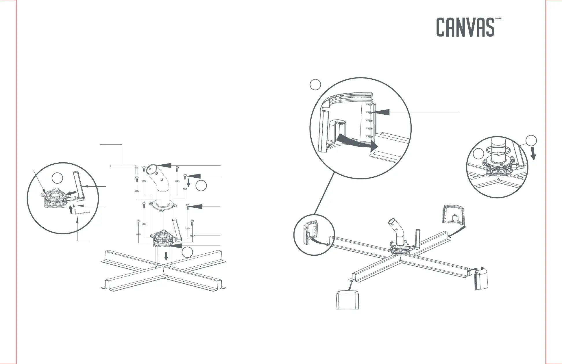
Step 3
Requires J
Insert corner connector (J) into the four ends of assembled brackets.
T
F
D
I
S
C
G
H
D
V
J
1
2
3
1
2
3
NOTE: Do not completely tighten.

 Loading...