EasyManua.ls Logo

CAP GEN-2 - User Manual

CAP GEN-2
5 pages
Print Icon
To Next Page IconTo Next Page
Loading...
Mark
The GEN-2 can produce between 16-26 cubic feet of CO
2
per hour. It is
recommended for rooms up to 36’ x 36’ (approximate)
Features a “two-stage” safety pilot valve, which will not allow fuel to flow to the
burner unless the pilot is lit.
Our standard “tip-over” switch will shut down the fuel to the main burner in the
event the unit falls or tips over.
The GEN-2 can be expanded by adding additional burners.
Manufactured in the USA using only AGA and UL listed components.
INSTALLATION
1) Determine the desired location for the generator. It must be positioned at least 18” away from walls or other flammable
materials. A distance of at least 18” must be maintained between the top of the unit and the
ceiling or roof. Open flames are present inside the unit. Do not use the unit around
flammable materials.
2) The unit must be hung from suitable supports. Use at least two chains / hooks to secure the
unit. The unit must be level in order to operate correctly and safely.
3) The hose that is supplied with the generator is fitted with a standard 3/8” female flare
connection. Connect the gas hose to the back of the CO
2
generator. To connect the hose, use
two wrenches in order to properly tighten the connection without twisting any internal
connections.
PROPANE
Connect the other end of the hose to the LP regulator supplied with the unit. To connect the hose, use two wrenches in
order to properly tighten the connection.
Open the gas valve on the propane tank. Check for leaks on all connections using a spray bottle with soapy water. Look for
bubbles, which would indicate a leak.
NATURAL GAS
Make certain that you have a gas shut-off valve on your gas supply. Install the shut-off valve in an accessible location.
Install the in-line regulator to the gas supply, (3/8” NPT female thread). Connect the hose to the in-line regulator. To connect
the hose, use two wrenches in order to properly tighten the connection.
Open the gas valve on the gas line. Check for leaks on all connections using a spray bottle with soapy water. Look for
bubbles, which would indicate a leak.
CAP’s CO
2
generators economically and safely produce carbon dioxide by burning eithe
r
P
ropane or Natural Gas. We have designed our CO
2
generator to allow you to increase the
CO
2
production simply by installing additional burners.
GEN-2 CO
2
Generator
WARNING
Connecting propane to a generator meant to burn natural gas will result in dangerously large flames. Alternately if natural
gas is connected to a generator meant to burn propane will result in inconsistent flames with too little fuel available to
b
urn properl
y
. Make sure fuel suppl
y
matches the
y
our
g
enerator t
y
pe!!!
NOTE: The GEN-2 propane model comes with a standard tank mounted regulator, which must be used unless the LP
pressure is already regulated to 11” WC pressure at an outdoor propane tank.
NOTE: It is critical to install the regulator supplied “in-line” between your gas supply and the generator. The regulator
supplied with the GEN-2 is preset to maintain a constant pressure of 4.5” WC, which is around ¼ PSI. It is important to
verify the main gas pressure before installing the unit. Most gas utility companies install low-
p
ressure gas regulators on the
main gas line that are set up to ½ PSI, (4.5 - 7” WC). Some commercial buildings have a high-pressure gas main (usually
2PSI). If this is this case, you will need to have the pressure reduced to ½ PSI or lower before installing the low-pressure
regulator supplied with the unit.
Question and Answer IconNeed help?

Do you have a question about the CAP GEN-2 and is the answer not in the manual?

Summary

INSTALLATION

PROPANE Setup

Instructions for connecting and operating the GEN-2 generator with propane.

NATURAL GAS Setup

Instructions for connecting and operating the GEN-2 generator with natural gas.

GENERATOR OPERATION

LIGHTING THE PILOT FLAME

Guide to safely ignite the pilot flame, essential for main burner operation.

OPERATING YOUR GENERATOR

Details on running the generator, CO2 levels, and controller integration.

GENERATOR MAINTENANCE

FRONT BURNER ACCESS PANEL

Procedure for accessing the burner assembly by removing the front panel.

SAFETY AND OTHER FEATURES

SAFETY FEATURES

Overview of built-in safety mechanisms like pilot safety valve and tip-over switch.

OTHER FEATURES

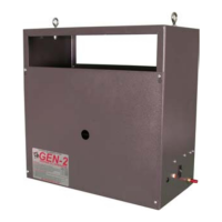
Details on powder-coated enclosure, visual appearance, serviceability, and conversions.

SIZING AND EXPANSION

PROPER SIZING

Guidance on calculating CO2 output and factors affecting generator performance.

EXPANDING; ADDING BURNERS

Information on increasing CO2 production by installing additional CAP burners.

CONTROLLER OPTIONS

TROUBLESHOOTING AND PRECAUTIONS

TROUBLESHOOTING

Common problems and suggested solutions for generator issues.

PRECAUTIONS

Important safety warnings and guidelines for operating the generator.

WARRANTY AND SPECIFICATIONS

WARRANTY

Details on the warranty period for the GEN-2 CO2 generator.

GEN-2 SPECIFICATIONS

Technical specifications including power, pressure, BTU, and dimensions.

Overview

The GEN-2 CO2 Generator, manufactured by R & M Supply Inc. under the C.A.P. brand, is designed to economically and safely produce carbon dioxide by burning either propane or natural gas. Its modular design allows users to increase CO2 production by simply installing additional burners.

Function Description:

The primary function of the GEN-2 is to generate CO2 for environmental enrichment, typically in controlled growing environments. It operates by burning fuel (propane or natural gas) to produce CO2. The unit is designed with safety in mind, incorporating several features to ensure safe operation. It can be integrated with CO2 controllers to maintain desired PPM levels, optimizing plant growth while preventing excessive CO2 concentrations.

Important Technical Specifications:

  • CO2 Production: The GEN-2 can produce between 16-26 cubic feet of CO2 per hour, suitable for rooms up to 36' x 36' (approximate).
  • Power Supply:
    • Input: 120vac
    • Output: 18-24vdc
  • Gas Pressure:
    • Propane: 11" WC
    • Natural Gas: 4.5" WC
  • BTU Ratings (Propane / Natural Gas):
    • 5 burner: 13,970 / 15,675 BTU
    • 6 burner: 16,764 / 18,810 BTU
    • 7 burner: 19,558 / 21,945 BTU
    • 8 burner: 22,352 / 25,080 BTU
  • Weight: 16 lbs.
  • Dimensions: 16 ½" x 16 ½" x 8 ½"
  • Components: Manufactured in the USA using only AGA and UL listed components.

Usage Features:

  • Fuel Type: Available in models for either propane or natural gas. It is crucial to match the fuel supply to the generator type to avoid dangerously large or inconsistent flames. Conversion kits (LPC-1 & NGC-1) are available to switch between LP and natural gas operation.
  • Installation:
    • Must be positioned at least 18" away from walls or other flammable materials, and 18" from the ceiling/roof.
    • Requires hanging from suitable supports, using at least two chains/hooks, and must be level for correct and safe operation.
    • Gas hose connection uses a standard 3/8" female flare connection, requiring two wrenches for proper tightening.
    • For propane models, a standard tank-mounted regulator is supplied and must be used unless LP pressure is already regulated to 11" WC at an outdoor tank.
    • For natural gas models, an in-line regulator (preset to 4.5" WC, ~¼ PSI) is supplied and must be installed between the gas supply and the generator. Main gas pressure should be verified to be around ½ PSI or lower before installation.
    • All gas connections must be checked for leaks using soapy water and a spray bottle.
  • Lighting the Pilot Flame:
    • Connect power supply to the generator and plug into a wall outlet or CO2 controller.
    • Ensure the power switch is OFF and turn ON the gas supply.
    • Access pilot flame through one-inch holes on the front/back of the unit.
    • Use an extended tip lighter to apply flame to the pilot burner tube.
    • Press and hold the red button on the pilot safety valve for up to a minute to allow gas flow and thermocouple heating. The pilot will remain lit once the thermocouple is hot enough.
    • Once the pilot is lit, turning the power switch ON activates the main burner valve, igniting the main burners.
  • Operation:
    • Recommended CO2 level for optimum growth is 1000-1500 PPM. Levels above 5000 PPM are dangerous.
    • Connect the generator's power supply to a CO2 controller (e.g., CO2-2, PPM-3) or a time clock/photo-controller to ensure operation only during daylight hours and to maintain desired PPM levels.
    • Turning the power switch ON activates the main burner solenoid valve. An amber pilot light indicates the main burner is running.
  • Expandability: The GEN-2 allows for increasing CO2 production by adding additional CAP brass burners, each adding approximately 3 cubic feet of CO2 per hour.
  • Propane Crossover (PXO-1): An optional assembly allows running the generator off two propane tanks, enabling simultaneous use or selection of one tank to avoid re-lighting the pilot flame during tank changes.

Safety Features:

  • Two-Stage Safety Pilot Valve: Ensures the pilot flame is present before gas flows to the main burner, preventing dangerous "fume explosions."
  • Tip-Over Shut-Off Switch: Shuts off fuel to the main burner if the unit tilts more than 35 degrees in any direction.
  • AGA Approved Devices: All gas components are AGA approved for both LP and Natural gas.
  • High-Quality Fittings: Uses fine brass fittings and heavy-duty hoses.
  • Type I LP Tank Connector: Incorporates a "flow-limiting" device (reduces flow to 10 SCFH in case of a leak) and a heat-sensing spring-loaded module (stops gas flow if temperature exceeds 240°F).
  • Warning for Fuel Mismatch: Clearly warns against connecting propane to a natural gas generator or vice-versa due to safety risks.
  • Enclosure Heat Warning: The outer enclosure gets hot during operation; do not touch until cool.
  • CO2 Level Precautions: Advises against allowing CO2 levels to rise above 2500 ppm and recommends operating in safe, ventilated environments.
  • Carbon Monoxide Alarm: Recommended if operating in areas with limited ventilation.

Maintenance Features:

  • Durable Construction: Powder-coated steel enclosure for a long-lasting finish that resists fading and allows heat dissipation. Brass burners are used for superior, long-term performance compared to steel.
  • Cleaning: The powder-coated enclosure can be cleaned with normal cleaners.
  • Easily Serviceable: Two access points (front and back) allow pilot light ignition from outside the unit using an extended tip lighter. The entire front cover can be easily removed (four screws) to expose the burner assembly for adding burners or servicing.
  • User Serviceability Warning: States there are no user-serviceable parts inside the generator and advises against attempting to service gas components. If the unit is not performing correctly, users should consult the troubleshooting guide or contact a qualified gas serviceman.
  • Cool-Down Requirement: Always wait for the generator to cool down properly before servicing or removing the front panel.
  • Leak Checks: Regular checks for leaks on all connections using soapy water are recommended.

CAP GEN-2 Specifications

General IconGeneral
BrandCAP
ModelGEN-2
CategoryInverter
LanguageEnglish