with appropriate fixings (ducting and fixings are not provided and are to be supplied by the
installer). The ducting (Fig.6A) must be connected with the cooker hood placed in the kitchen,
and the ducting (Fig.6B) must be directed outside the building.
the wiring. Make sure to respect the colours of the cables when performing the electrical
connection (Fig.7).
INSTALLING THE APPLIANCE:
After deciding the position and the type of installation, insert
the anti-vibration rubber caps in the holes of the brackets
supplied (Fig.5C).
The rubber caps must be put on the sides which are in
contact with the wall.
Put the brackets (Fig.5A) on the remote fitted extraction
motor by matching its holes with those of the brackets. Fix
with the screws supplied (Fig.5B).
Put the group on the point previously chosen for the
installation and mark the points on the wall where the holes
must be drilled.
Insert the dowels supplied in the holes (Fig.4A). Put the
remote fitted extraction motor on the wall by matching the
holes of the brackets with the plastic dowels. Screw with
the screws supplied (Fig.4B).
A
B
C
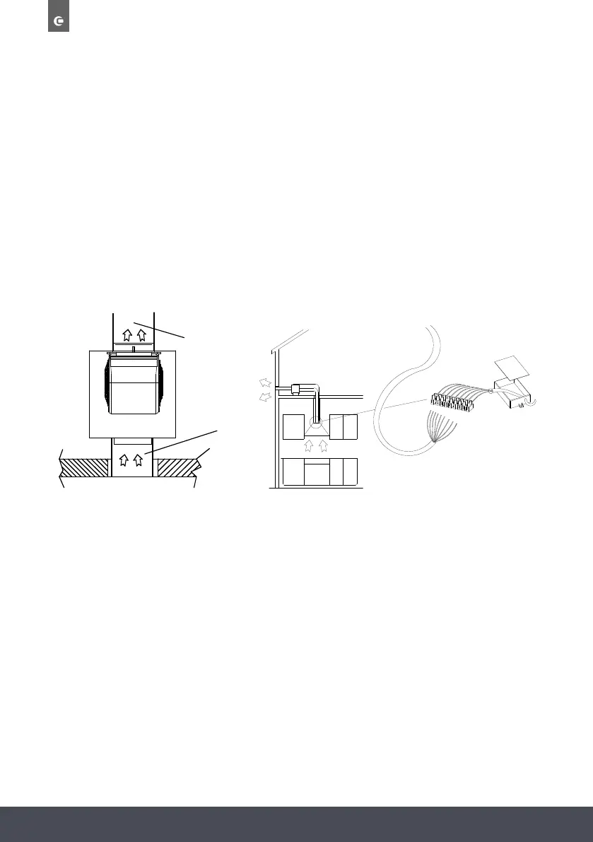
CONNECTING THE DUCTING:
The appliance has an inlet and an outlet to connect the ducting. Before connecting the ducting, check the direction of
the air shown on the rating label (Fig.6). Connect the ducting with appropriate fixings (ducting and fixings are not
provided and are to be supplied by the installer). The ducting (Fig.6A) must be connected with the cooker hood placed
in the kitchen, and the ducting (Fig.6B) must be directed outside the building.
Connect the external motor’s cable to the terminal board found inside the plastic box of the wiring. Make sure to
respect the colours of the cables when performing the electrical connection (Fig.7).
FIG.5
 Loading...