Do you have a question about the caprari PM Series and is the answer not in the manual?
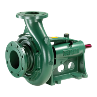
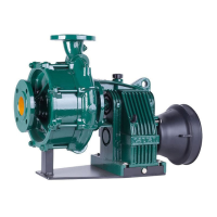
This manual describes the Caprari PM...(S) series of horizontal shaft pumps, designed for industrial, aqueduct, and irrigation applications, or similar uses. These pumps are engineered for pumping clear water from collection tanks or for pressure boosting.
The PM...(S) series pumps are multistage centrifugal pumps, featuring two or more hydraulically balanced impellers arranged in series. They operate with a clockwise rotation when viewed from the shaft projection side, as indicated by an arrow on the delivery casing. The delivery port is radial and vertical, while the suction port is radial and oriented to the right relative to the shaft projection. The pumps are equipped with a shaft supported by grease-lubricated rolling bearings and can be coupled to an electric motor or an internal combustion engine via a coupling or transmission shaft.
Special versions are available upon request, including:
The pump's data plate provides key information:
For the motor, the data plate includes:
The pumps are designed for continuous service (S1) and are not suitable for dry operation or pumping liquids other than clear, chemically and mechanically non-aggressive water. They can handle water with a solids concentration up to 20 g/m³ (20 parts/million) with packing seals, but 0 g/m³ for mechanical seal versions. The maximum allowable liquid temperature is 90 °C (194 °F). Operation in classified explosion risk areas requires appropriately equipped explosion-proof motors and control circuits. The pump should not be operated with the port closed for extended periods, especially with liquid temperatures at 90 °C. For a liquid temperature of 40 °C, the maximum operating time with a closed port is 6 minutes at 1450 min⁻¹ and 2 minutes at 2900 min⁻¹. The system requires proper installation, ensuring adequate ventilation if installed in an enclosed space, easy inspection, and the use of an elastic transmission coupling. For noise reduction, the pump should be connected to pipes with vibration damping compensators. Protection against freezing is essential, or the system must be completely drained. When pumping hot liquids, surfaces exceeding 80 °C must be protected to prevent burns. For correct operation, the suction pressure must meet the required NPSH conditions, and the dynamic water level in collection tanks must be sufficient to prevent vortex formation (minimum submersion 0.5 m). The delivery pipe must include a quick-closing check valve, an on-off sluice valve, and a pressure gauge. The suction pipe should prevent air pockets and excessive head losses, and if the pump is installed above water level, it must have a foot valve for priming. When using an INVERTER, the minimum frequency during starting and operation must not be less than 70% of the rated value. The motor must be ordered with the appropriate electric winding. The voltage gradient should be ≤ 750 V/µs, with harmonic content of voltage ≤ 1.5% and current ≤ 4%. The rotation direction must be checked during startup. An incorrect rotation direction can damage the motor and pump due to significantly higher power draw and axial thrust than expected. To check, fill the pump and pipe with water, close the delivery sluice valve, and briefly start the electric pump. If the rotation is incorrect, disconnect the power source and switch two of the three live wires. Phase unbalance should not exceed 5%.
Routine maintenance and repairs must be carried out by specialized personnel. Extraordinary maintenance and repairs should be performed by authorized specialized workshops. Regular preventive inspections are recommended every 1000-1500 operating hours, or at least once a year. These inspections include:
If the pump is to remain inactive for 20-30 days, ensure the rotor is free to turn and the hydraulics are primed before restarting. If there is a risk of freezing, the pump and ducts must be completely emptied. For disassembly, the pump must always be disassembled starting from the delivery side and reassembled starting from the suction side. When removing the transmission coupling, avoid tapping the shaft projection; use pullers that only lever on the pump shaft and its threaded end. Replacing the packing seal involves removing the adjuster nuts, sliding the gland, replacing the packing material, and then readjusting the gland evenly while the machine is running to ensure slight dripping. Replacing the mechanical seal requires contacting an authorized after-sales service center. Only genuine Caprari spare parts should be used for repairs to maintain warranty coverage. When ordering spare parts, provide the complete product code, date code, serial number, job number, part denomination, reference number from the spare parts catalog, and the quantity required.
| Brand | caprari |
|---|---|
| Model | PM Series |
| Category | Water Pump |
| Language | English |