Do you have a question about the CAR-connect VAS 5581A and is the answer not in the manual?
Details regarding the operating manual and product delivery.
Explains the scope and validity of the product's declaration of conformity.
Information about the manufacturer, CAR-connect GmbH, and its expertise.
Explains the different warning levels used in the manual (DANGER, WARNING, CAUTION).
Details critical safety instructions for handling the product, especially regarding electrical hazards.
Describes the safety features of the diagnostic box, including the emergency stop button.
Defines the proper and prohibited uses of the diagnostic box as per manufacturer guidelines.
Specifies the qualifications and training required for personnel using the product.
Outlines the responsibilities of the operator for ensuring safe and proper use of the device.
Lists supplementary documentation provided with the diagnostic box.
Lists all items included in the product package with corresponding identifiers.
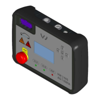
Details the physical design and labeled components of the diagnostic box.
Describes the different types of power supply cables provided based on country usage.
Details the adapter cable and lists available product sets with item numbers.
Explains the meaning of stickers, labels, and port identifiers on the product.
Details the various displays (lights, indicators, LC display) and physical controls on the diagnostic box.
Explains the function of each control and provides a breakdown of pin connections.
Lists key technical specifications, dimensions, weight, and environmental operating conditions.
Provides step-by-step instructions for setting up the diagnostic box before operation.
Instructions on how to power on the diagnostic box and check its battery status.
Guide to connecting the power supply and charging the internal battery pack.
Explains how to navigate menus, use buttons, and control keys on the LC display.
Illustrates menu organization and details available operating modes like Soft/Gateway/Hard bridge.
Explains the soft bridge mode and its communication behavior with vehicle components.
Describes the gateway mode, its communication protocol, and data handling.
Details the hard bridge mode, emphasizing direct hardware connection without isolation.
Covers connecting vehicle components and initiating diagnostic procedures.
Procedure for supplying power to the component being tested via terminals 30 and/or 15.
Steps for additional connection configurations, including pilot line and high-voltage relay.
Instructions for closing the pilot line and energizing high-voltage circuits safely.
How to set the CAN termination resistor to 120 ohms or infinite.
Steps to connect the VC interface to the diagnostic box for communication.
Procedures for safely concluding diagnostic sessions and shutting down the device.
Instructions on how to turn off the diagnostic box using the main switch.
Step-by-step guide on how to safely disconnect cables from the diagnostic box.
Guidelines for cleaning, proper storage, transportation, and responsible disposal of the device.
Information on regular maintenance, testing, and replacing the Li-ion battery pack.
Crucial information on correctly orienting battery cells during installation to prevent damage.
Details the warranty period, conditions, and how to find further information.
Provides contact information for customer support, including phone, fax, and email.
| Brand | CAR-connect |
|---|---|
| Category | Diagnostic Equipment |
| Model | VAS 5581A |
| Function | Vehicle diagnostics |
| Interface | USB |
| Supported Protocols | CAN, KWP2000, UDS |