IR32V0H000
IR32V0L00
IR32W00000
IR32Z00000
IR32A00000
IR32D00000
IR33V7HR20
IR33V7LR20
IR33W7LR20
IR33Z7LR20
IR33A7LR20
IR33D7LR20
ir33 ir32
The CAREL product is a state-of-the-art device, whose operation is specifi ed in the user manual code
+03022080* which can be downloaded, even prior to purchase, from the website www.carel.com.
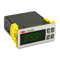
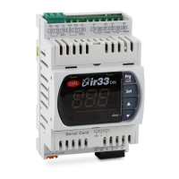
Description: these instructions explain how to replace a IR32 universale family controller with the
corresponding new controller from the IR33 universale family
Table of equivalent models:
ir32 ir33
Type Code Description Code Description
1 Relay
IR32V0H000
110 to 230 V, 2 NTC, 1 relay, IR,
buzzer
IR33V7HR20 115 to 230 V 2 NTC/PTC, 1 relay, buzzer, IR
IR32V0L000 12 to 24 V, 2 NTC, 1 relay, IR, buzzer IR33V7LR20 12 to 24 V, 2 NTC/PTC, 1 relay, buzzer, IR
2 Relay IR32W00000 12 to 24 V, 2 NTC, 2 relays, IR, buzzer IR33W7LR20 12 to 24 V, 2 NTC/PTC, 2 relay, buzzer, IR
4 Relay IR32Z00000 12 to 24 V, 2 NTC, 4 relays, IR, buzzer IR33Z7LR20 12 to 24 V, 2 NTC/PTC, 4 relay, buzzer, IR
4 SSR IR32A00000 12 to 24 V, 2 NTC, 4 SSR, IR, buzzer IR33A7LR20
12 to 24 V, 2 NTC/PTC, 4 SSR,
buzzer, IR
1 SSR IR32D0L000 12 to 24 V, 2 NTC, 1 SSR, IR, buzzer IR33D7LR20
12 to 24 V, 2 NTC/PTC, 1 SSR,
buzzer, IR
1 Relay +
1 0 to 10 V
IR32D0L000 + 1 CONV0/10A0 IR33B7LR20
12 to 24 V, 2 NTC/PTC, 1 relay + 1 AO,
buzzer, IR
2 Relay +
2 0 to 10 V
IR32A00000 + 2 CONV0/10A0
+2 CONVONOFF0
IR33E7LR20
12 to 24 V, 2 NTC/PTC, 2 relay + 2 AO,
buzzer, IR
The IR33 universale family is more complete than the IR32 Universale family.
The same IR32 model may correspond to more than one model of IR33 with different options or
including the special modules (CONV…).
1. Electrical connections
The equivalence of the electrical connections is shown in the fi rst column of this sheet.
The IR32 Universale models are fi tted with screw terminals, while the IR33 universale models have
plug-in screw terminals.
REPLACEMENT EXAMPLE : models IR32V0L000 and IR33V7LR20 differ due to the relay, which is
indicated respectively as OUT1 (common on terminal 2) and DO1 (common on terminal 1), the
probe, indicated as NTC1 and B1, the digital input indicated as DIG.IN and DI1, and the power supply
terminals in different positions.
2. Programming
The IR33 universale has all the functions of the IR32 Universale, plus additional functions concerning
the on and off limits (parameters with code “d”) and all the parameters after c51. All the parameters
on the IR33 Universale maintain the same meaning as those on the IR32 Universale. Therefore, simply
enter the same values for the parameters that are valid for the IR32 Universale and the new IR33
Universale will work in the same way. To access “Programming” mode:
1)Press Prg/mute and Set together and hold for 5 seconds
2)Enter the password (77). Confi rm by pressing Set
3)Press UP and DOWN to reach the parameter to be changed from the default setting
4)Once having reached the required parameter, press Set; the value fl ashes
5)Press UP and DOWN to change the value, valore, confi rm by pressing Set
6)To set another parameter, repeat steps 3),4),5)
7)To permanently save the values and exit ”Programming” mode, press Prg/mute for 5 seconds
Disposal: The appliance (or the product) must be disposed of separately in compliance with
the local standards in force on waste disposal.
IMPORTANT WARNINGS: The CAREL product is a state-of-the-art device, whose operation is
specifi ed in the technical documentation supplied with the product or can be downloaded, even prior
to purchase, from the website www.carel.com. The customer (manufacturer, developer or installer of
the fi nal equipment) accepts all liability and risk relating to the confi guration of the product in order to
reach the expected results in relation to the specifi c fi nal installation and/or equipment. The failure to
complete such phase, which is required/indicated in the user manual, may cause the fi nal product to
malfunction; CAREL accepts no liability in such cases. The customer must use the product only in the
manner described in the documentation relating to the product. The liability of CAREL in relation to its
products is specifi ed in the CAREL general contract conditions, available on the website www.carel.com
and/or by specifi c agreements with customers.
+050003095 - rel 1.1 - 17-11-2008
ir33 Universale - ir32 Universale Istruzione per la sostituzione/Replacement instructions/Instruction pour le remplacement/Austauschanleitung/Instrucciones para la sustitución
Il prodotto CAREL è un un prodotto avanzato, il cui funzionamento è specifi cato nel manuale
d’uso cod. +03022080* scaricabile, anche anteriormente all’acquisto, dal sito www.carel.com.
Descrizione: la presente istruzione spiega come effettuare la sostituzione di un regolatore della famiglia
IR32 universale con il corrispondente nuovo regolatore della famiglia IR33 universale
Tabella di corrispondenza:
ir32 ir33
Tipo Codice Descrizione Codice Descrizione
1 Relè
IR32V0H000 110...230 V, 2 NTC, 1 relè, IR, buzzer IR33V7HR20 115...230 V, 2 NTC/PTC, 1 relè, buzzer, IR
IR32V0L000 12...24 V, 2 NTC, 1 relè, IR, buzzer IR33V7LR20 12...24 V, 2 NTC/PTC, 1 relè, buzzer, IR
2 Relè IR32W00000 12...24 V, 2 NTC, 2 relè, IR, buzzer IR33W7LR20 12...24V, 2 NTC/PTC, 2 relè, buzzer, IR
4 Relè IR32Z00000 12...24 V, 2 NTC, 4 relaè, IR, buzzer IR33Z7LR20 12...24 V, 2 NTC/PTC, 4 relè, buzzer, IR
4 SSR IR32A00000 12...24 V, 2 NTC, 4 SSR, IR, buzzer IR33A7LR20 12...24V, 2 NTC/PTC, 4 SSR, buzzer, IR
1 SSR IR32D0L000 12...24 V, 2 NTC, 1 SSR, IR, buzzer IR33D7LR20 12...24V, 2 NTC/PTC, 1 SSR, buzzer, IR
1 Relè +
1 0
…10V
IR32D0L000 + 1 CONV0/10A0 IR33B7LR20
12...24V, 2 NTC/PTC, 1 relè + 1 AO,
buzzer, IR
2 Relè +
2 0
…10V
IR32A00000 + 2 CONV0/10A0
+2 CONVONOFF0
IR33E7LR20
12...24V, 2 NTC/PTC, 2 relè + 2 AO,
buzzer, IR
La famiglia IR33 universale è più completa della famiglia dell’IR32 Universale.
E’ possibile che allo stesso modello IR32 corrispondano più modelli dell’IR33 con diverse opzioni o che
i moduli speciali (CONV…) siano integrati.
1. Collegamenti elettrici
La corrispondenza dei collegamenti elettrici è riportata nella prima colonna di questo foglio.
I modelli IR32 Universale sono provvisti di morsetti fi ssi a vite, mentre i modelli IR33 universale hanno
morsetti estraibili a vite.
ESEMPIO PER LA SOSTITUZIONE : i modelli IR32V0L000 e IR33V7LR20 differiscono per il relè che è
indicato rispettivamente con OUT1( comune su morsetto 2) e DO1(comune su morsetto 1), per la
sonda indicata con NTC1 e B1, per l’ingresso digitale indicato con DIG.IN e DI1 e per i morsetti dell’
alimentazione in posizioni diverse.
2. Programmazione
L’IR33 universale ha tutte le funzioni dell’IR32 Universale più altre funzioni riguardanti i vincoli in
accensione e spegnimento (parametri con codice “d”) e tutti i parametri dopo il c51. Tutti i parametri
dell’IR33 Universale conservano lo stesso signifi cato dell’IR32 Universale. Pertanto basta reinserire gli
stessi valori dei parametri già validi per l’IR32 Universale e il nuovo IR33 Universale funzionerà allo
stesso modo. Per entrare in modalità “Programmazione”:
1)Premere contemporaneamente i tasti Prg/mute e Set per 5 secondi
2)Inserire la password (77). Confermare con Set
3)Premere UP e DOWN per raggiungere i parametri da modifi care rispetto all’impostazione di fabbrica(default)
4)Raggiunto il parametro da modifi care, premere Set, il valore lampeggia
5)Con i tasti UP e DOWN modifi care il valore, confermare con Set
6)Per modifi care un altro parametro ripetere i passi 3),4),5)
7)Per memorizzare defi nitivamente i valori ed uscire dalla modalità”Programmazione”, premere Prg/mute
per 5 secondi
Smaltimento: L’apparecchiatura (o il prodotto) deve essere oggetto di raccolta separata in
conformità alle vigenti normative locali in materia di smaltimento.
AVVERTENZE IMPORTANTI
Il prodotto CAREL è un prodotto avanzato, il cui funzionamento è specifi cato nella documentazione
tecnica fornita col prodotto o scaricabile, anche anteriormente all’acquisto, dal sito internet www.
carel.com. Il cliente (costruttore, progettista o installatore dell’equipaggiamento fi nale) si assume ogni
responsabilità e rischio in relazione alla fase di confi gurazione del prodotto per il raggiungimento dei
risultati previsti in relazione all’installazione e/o equipaggiamento fi nale specifi co.La mancanza di tale
fase di studio, la quale è richiesta/indicata nel manuale d’uso, può generare malfunzionamenti nei
prodotti fi nali di cui CAREL non potrà essere ritenuta responsabile.Il cliente fi nale deve usare il prodotto
solo nelle modalità descritte nella documentazione relativa al prodotto stesso. La responsabilità di
CAREL in relazione al proprio prodotto è regolata dalle condizioni generali di contratto CAREL editate
nel sito www.carel.com e/o da specifi ci accordi con i clienti.