+05Z0028EN- rel. 1.0 - 13.03.2014
CAREL INDUSTRIES HQs
Via dell’Industria, 11 - 35020 Brugine - Padova (Italy)
Tel. (+39) 0499716611 – Fax (+39) 0499716600 – http://www.carel.com – e-mail: carel@carel.com
CAREL reserves the right to modify the features of its products without prior notice.
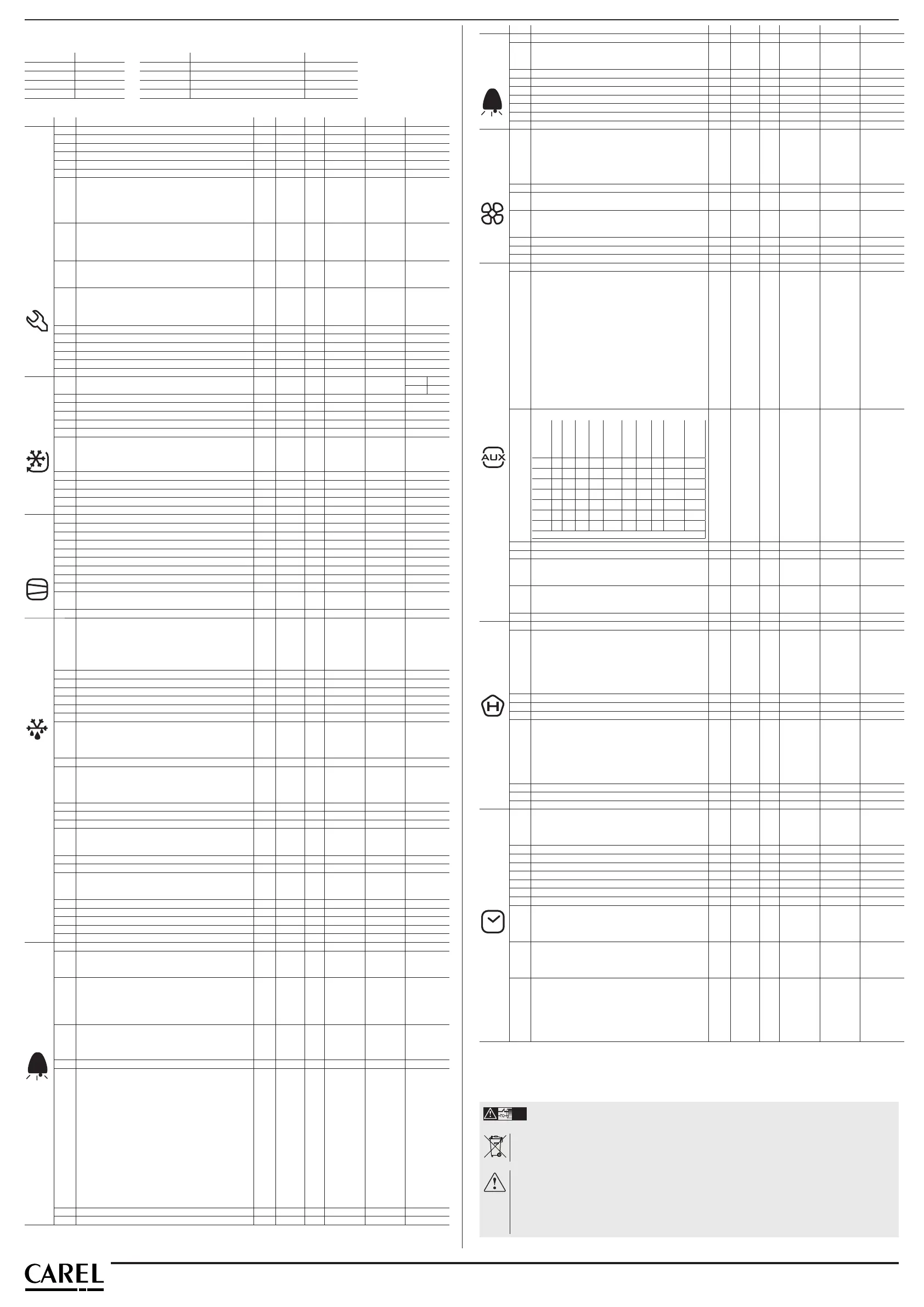
Parameters
Default settings table
Part number Def. settings Part number Def. settings Part number Def. settings
IREVM0LN0U - IREVC0LN0U Def. 2 IREVF0EN0U Def. 2
IREVM0EN0U - IREVC0LC0U Def. 2
IREVS0LN0U Def. 1 IREVC0HN0U Def. 2
IREVS0EA0U Def. 1 IREVC0HC0U Def. 2
Summary of operating parameters (UOM = Unit of measure; Def. = Default value)
Symbol Code Parameter Mod. UOM Type Min. Max. Def.
Pw Password MSYF - C 0 200 22
/2 Measurement stability MSYF - C 1 15 4
/3 Probe display response MSYF - C 0 15 0
/4 Virtual probe MSYF - C 0 100 0
/5 Selection °C o °F (0: °C ,1: °F) MSYF fl ag C 0 1 0
/6 Display decimal point 0= YES, 1=NO MSYF fl ag C 0 1 0
/tI Display on internal terminal
1: virtual probe; 5: probe 4
2: probe 1 6: probe 5
3: probe 2 7: set point
4: probe 3
MSYF - C 1 7 1
/tE Display on external terminal remote terminal not present
1: virtual probe 4: probe 3
2: probe 1 5: probe 4
3: probe 2 6: probe 5
MSYF - C 0 6 0
/P Select type of probe
0: NTC standard with range -50T90°C
1: NTC enhanced with range -40T150°C
MSYF - C 0 2 0
/A2 Confi guration of probe 2 (S2)
0: probe absent 3: condenser probe
1: product probe (display only) 4: antifreeze probe
2: defrost probe
MS
YF
-
-
C
C
0
0
4
4
0
2
/A3 Confi guration of probe 3 (S3/DI1) As for /A2 MSYF - C 0 4 0
/A4 Confi guration of probe 4 (S4/DI2) As for /A2 MSYF - C 0 4 0
/c1 Calibration of probe 1 MSYF °C/°F C -20 20 0.0
/c2 Calibration of probe 2 MSYF °C/°F C -20 20 0.0
/c3 Calibration of probe 3 MSYF °C/°F C -20 20 0.0
/c4 Calibration of probe 4 MSYF °C/°F C -20 20 0.0
St Temperature Set Point MSYF °C/°F F r1 r2 Def 1 Def 2
2 -18
rd Control delta (diff erential) SYF °C/°F F 0,1 20 2,0
r Dead band SYF °C/°F C 0,0 60 4,0
rr Reverse diff erential for control with dead band SYF °C/°F C 0,1 20 2,0
r1 Minimum set point allowed MSYF °C/°F C -50 r2 -50
r2 Maximum set point allowed MSYF °C/°F C r1 200 60
r3 Operating mode
0: Direct (cooling) with defrost control
1: Direct (cooling)
2: Reverse-cycle (heating)
SYF fl ag C 0 2 0
r4 Automatic night-time set point variation MSYF °C/°F C -20 20 3,0
r5 Enable temperature monitoring: 0: disabled, 1: enabled MSYF fl ag C 0 1 0
rt Temperature monitoring interval MSYF hr F 0 999 -
rH Maximum temperature read MSYF °C/°F F - - -
rL Minimum temperature read MSYF °C/°F F - - -
c0 Compressor, fan and AUX delay on start-up SYF min C 0 15 0
c1 Minimum time between successive starts SYF min C 0 15 0
c2 Min. compressor OFF time SYF min C 0 15 2
c3 Minimum compressor ON time SYF min C 0 15 0
c4 Duty setting SYF min C 0 100 0
cc Continuous cycle duration SYF hr C 0 15 0
c6 Alarm bypass after continuous cycle SYF hr C 0 250 2
c7 Maximum pump down time SYF s C 0 900 0
c9 Enable autostart function in PD SYF fl ag C 0 1 0
c10 Select Pump down by time or pressure
0: Pump down by pressure; 1: Pump down by time
SYF fl ag C 0 1 0
c11 Second compressor delay SYF s C 0 250 4
d0 Type of defrost
0: Electric heater defrost by temperature
1: Hot gas defrost by temperature
2: Electric heater defrost by time
3: Hot gas defrost by time
4: Electric heater defrost thermostat by time
SYF fl ag C 0 4 0
dI Interval between defrosts SYF hr F 0 250 8
dt1 End defrost temperature, evaporator SYF °C/°F F -50 200 4,0
dt2 End defrost temperature, aux evaporator SYF °C/°F F -50 200 4,0
dP1 Maximum defrost duration, evaporator SYF min F 1 250 30
dP2 Maximum defrost duration, aux evaporator SYF min F 1 250 30
d3 Defrost start delay SYF min C 0 250 0
d4 Enable defrost on start-up
0: No defrost when the instrument is switched on
1: A defrost is performed when the instrument is
switched on
SYF fl ag C 0 1 0
d5 Defrost delay on start-up SYF min C 0 250 0
d6 Display on hold during defrost
0: Alternating display of dEF and probe value
1: Display of the last temp. shown
2: Display of dEF steady
SYF - C 0 2 1
dd Dripping time after defrost SYF min F 0 15 2
d8 Alarm bypass after defrost SYF hr F 0 250 1
d8d Alarm bypass after door open SYF min C 0 250 0
d9 Defrost priority over compressor protectors
0: The protection times c1, c2 and c3 are observed
1: The protection times c1, c2 and c3 are not observed
SYF fl ag C 0 1 0
d/1 Display of defrost probe 1 MSYF °C/°F F - - -
d/2 Display of defrost probe 2 MSYF °C/°F F - - -
dC Time base for defrost
0: dI in hours, dP1 and dP2 in minutes
1: dI in minutes, dP1 and dP2 in seconds
SYF fl ag C 0 1 0
d10 Compressor running time SYF hr C 0 250 0
d11 Running time temperature threshold SYF °C/°F C -20 20 1,0
d12 Advanced defrost SYF - C 0 3 0
dn Nominal defrost duration SYF - C 1 100 65
dH Proportional factor, variation in dI SYF - C 0 100 50
A0 Alarm and fan diff erential MSYF °C/°F C 0,1 20 2,0
A1 Type of threshold ‘AL’ and ‘AH’
0: AL and AH are relative thresholds to the set point
1: AL and AH are absolute thresholds
MSYF fl ag C 0 1 0
AL Low temperature alarm threshold MSYF °C/°F F A1=1-50
(alarm ‘LO’
disabled)
A1=0 0
(alarm ‘LO’
disabled)
200 0,0
AH High temperature alarm threshold MSYF °C/°F F A1=1-50
A1=0 0
(alarm ‘HI’
disabled)
A1=1200
(alarm ‘HI’
disabled)
A1=0200
0,0
Ad Low and high temperature alarm delay MSYF min F 0 250 120
A4 Digital input 1 confi guration (DI1)
0: Input not active
1: Immediate external alarm
2: Delayed external alarm
3: If model M, probe selection
3: Other models enable defrost
4: Start defrost
5: Door switch with compressor and fan stop - light managed
6: Remote ON/OFF
7: Curtain switch
8: Low pressure switch
9: Door switch with fan stop only- light managed
10: Direct/reverse
11: Light sensor
12: Activation of the AUX output
13: Door switch with compressor and fans off and light not
managed
14: Door switch with fans only off and light not managed
SYF
M
-
-
C
C
0
0
14
14
0
3
A5 Digital input 2 confi guration (DI2) / As for A4 MSYF - C 0 14 0
A6 Stop compressor from external alarm SYF min C 0 100 0
Disposal of the product
The appliance (or the product) must be disposed of separately in compliance with the local standards in force on waste disposal.
Important warnings:
The CAREL product is a state-of-the-art device, whose operation is specifi ed in the technical documentation supplied with the product or
can be downloaded, even prior to purchase, from the website www.carel.com. The customer (manufacturer, developer or installer of the fi nal
equipment) accepts all liability and risk relating to the confi guration of the product in order to reach the expected results in relation to the
specifi c fi nal installation and/or equipment. The failure to complete such phase, which is required/indicated in the user manual, may cause the
fi nal product to malfunction; CAREL accepts no liability in such cases. The customer must use the product only in the manner described in the
documentation relating to the product. The liability of CAREL in relation to its products is specifi ed in the CAREL general contract conditions,
available on the website www.carel.com and/or by specifi c agreements with customers.
WARNING: separate as much as possible the probe and digital input signal cables from the cables carrying inductive loads and power
cables to avoid possible electromagnetic disturbance. Never run power cables (including the electrical panel wiring) and signal cables
in the same conduits.
NO POWER
& SIGNAL
CABLES
TOGETHER
READ CAREFULLY IN THE TEXT!
Symbol Code Parameter Mod. UOM Type Min. Max. Def.
A7 External alarm detection delay SYF min C 0 250 0
A8 Enable alarms ‘Ed1’ and ‘Ed2’
A8=0 --> Alarm signals Ed1 and Ed2 disabled
A8=1 --> Alarm signals Ed1 and Ed2 enabled
SYF fl ag C 0 1 0
Ado Light management mode with door switch MSYF fl ag C 0 1 0
Ac High condenser temperature alarm SYF °C/°F C 0,0 200 70
AE High condenser temperature alarm diff erential SYF °C/°F C 0,1 20 10
Acd High condenser temperature alarm delay SYF min C 0 250 0
AF Light sensor OFF time SYF s C 0 250 0
ALF Antifreeze alarm threshold MSYF °C/°F C -50 200 -5
AdF Antifreeze alarm delay MSYF min C 0 15 1
F0 Fan management
0: Fans always on
1: Fans controlled according to the temperature diff eren-
ce between the virtual control probe and the evaporator
temperature
2: Fans controlled according to the evaporator temperature
Ffl agC 0 2 0
F1 Fan start temperature F °C/°F F -50 200 5
F2 Fan OFF with compressor OFF
0: Fans always on; 1: Fans off with compressor off
Ffl agC 0 1 0
F3 Fans in defrost
0: Fans operate during defrosts; 1: Fans do not operate
during defrosts
Ffl agC 0 1 1
Fd Fan Delay after dripping F min F 0 15 1
F4 Condenser fan stop temperature MSYF °C/°F C -50 200 40
F5 Condenser fan start diff erential MSYF °C/°F C 0,1 20 5
H0 Serial address MSYF - C 0 207 195
H1 Function of AUX output
0: Alarm output normally energised
1: Alarm output normally de-energised
2: Auxiliary output
3: Light output
4: Auxiliary evaporator defrost output
5: Pump down valve output
6: Condenser fan output
7: Delayed compressor output
8: Auxiliary output with deactivation when OFF
9: Light output with deactivation when OFF
10: No function associated with the output
11: Reverse output in control with dead band
12: Second compressor step output
13: Second compressor step output with rotation
MSYF fl ag C 0 13 1
H2 Disable keypad
Parameter
“H2”
LIGHT
ON/OFF
AUX
HACCP
PRG/MUTE
(mute)
UP/CC
DOWN/DEF
SET
parameter F
modi cation
Set point
modi cation
0
••
1
2
••
3
4
••••
5
•••••
6
•• • •
Keypad function “•” = Disabled
MSYF fl ag C 0 6 1
H4 Disable buzzer: 0: Buzzer enabled: 1: Buzzer disabled MSYF fl ag C 0 1 0
H6 Lock keypad MSYF - C 0 255 0
H8 Select activation of output with time band
0: Time band linked to output confi gured for light
1: Time band linked to output confi gured for aux
MSYF fl ag C 0 1 0
H9 Enable set point variation with time band
0: Set point variation with time band disabled
1: Set point variation with time band enabled
MSYF fl ag C 0 1 0
Hdh Anti-sweat heater off set MSYF °C/°F C -50 200 0
HAn Number of HA events recorded MSYF - C 0 15 0
HA
y__
M__
d__
h__
n__
t__
Date/time of last HA event
Year
Month
Day
Hour
Minute
Duration
MSYF -
years
months
days
hours
min
hours
C
0
1
1
0
0
0
-
99
12
7
23
59
99
-
0
0
0
0
0
0
HA1 Date/time of penultimate HA event MSYF - C - - -
HA2 Date/time of third-to-last HA event MSYF - C - - -
HFn Number of HF events recorded MSYF - C 0 15 0
HF
y__
M__
d__
h__
n__
t__
Date/time of last HF event
Year
Month
Day
Hour
Minute
Duration
MSYF -
years
months
days
hours
min
hours
C
0
1
1
0
0
0
-
99
12
7
23
59
99
-
0
0
0
0
0
0
HF1 Date/time of penultimate HF event MSYF - C - - -
HF2 Date/time of third-to-last HF event MSYF - C - - -
Htd HACCP alarm delay MSYF min C 0 250 0
td1
d__
h__
n__
Defrost time band 1
Day
Hour
Minute
SFY -
days
hours
min
C-
0
0
0
-
11
23
59
-
0
0
0
td2 Defrost time band 2 SFY - C - - -
td3 Defrost time band 3 SFY - C - - -
td4 Defrost time band 4 SFY - C - - -
td5 Defrost time band 5 SFY - C - - -
td6 Defrost time band 6 SFY - C - - -
td7 Defrost time band 7 SFY - C - - -
td8 Defrost time band 8 SFY - C - - -
ton
d__
h__
n__
Light/aux on time band, set point variance
Day
Hour
Minute
SFY -
days
hours
min
C-
0
0
0
-
11
23
59
-
0
0
0
toF
d__
h__
n__
Light/aux off time band, set point variance
Day
Hour
Minute
SFY -
days
hours
min
C-
0
0
0
-
11
23
59
-
0
0
0
tc
y__
M__
d__
u__
h__
n__
RTC date/time setting
Year
Month
Day of the month
Day of the week
Hour
Minute
MSYF -
years
months
days
days
hours
min
-
0
1
1
1
0
0
-
99
12
31
7
23
59
-
0
1
1
6
0
0
Important: for the set times to become immediately operational, the instrument must be turned off and on again.

 Loading...


