40
28.2
45
167
36
153.5
dima di foratura
drilling template
138.5 x 29mm
+0500019EN - rel. 3.4 del 07.02.2018
PB00**S* - powercompact small Models PB00(S, Y, F, C)(0,6)S(N,R,C,B,A,M,L,T)(0,1,2,3,4,5,A,B,C,D,E,F)0
Option codes
CODE DESCRIPTION
IRTRRES000 small remote control
IROPZ48500 RS485 serial inteface
IROPZ485S0 RS485 serial board interface with automatic recognition of the polarity +/-
IROPZDSP00 remote display interface
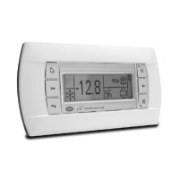
PST00VR100 remote repeater display
IR00RG0000 remote repeater display ir33 range green display
IR00RR0000 remote repeater display ir33 range red display
PSTCON01B0 repeater display connection cables 1,5 m
PSTCON03B0 repeater display connection cables 3 m
PSTCON05B0 repeater display connection cables 5 m
PSOPZKEY00 parameter programming key with extended memory and 12 V batteries included
PSOPZKEYA0 parameter programming key with 230 Vac power supply
IROPZKEY00 parameter programming key with 12 V battery included
IROPZKEYA0 parameter programming key with extended memory and external 230 Vac power supply
VPMSTDKY*0 key programming kit
Tab. 1
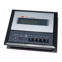
Display
powercompact uses a built-in display terminal with three LED digits and icon, to display the opera-
ting status. An additional display can be connected to the powercompact controller, via a suitable
interface for example to display the reading of a third probe.
Signals on the display
Icon Function
Normal operation
Start up
ON OFF blink
COMPRESS. compressor ON compressor OFF compressor request
FAN fan ON fan OFF fan request
DEFROST defrost ON defrost OFF defrost request
AUX
auxiliary output AUX
active
auxiliary output
AUX not active
anti-sweat heater
function active
ALARM
delayed external alarm
(before the expiry of
the time ‘A7’)
no alarm present
alarms in normal
operation (e.g. high/
low temperature) or
alarm from external
digital input, imme
-
diate or delayed
CLOCK
if at least 1 timed
defrost has been set
no timed defrost is clock alarm present
ON if real-
time clock
present
LIGHT
auxiliary output LIGHT
active
auxiliary output
LIGHT not active
anti-sweat heater
function active
SERVICE no malfunction
malfunction (e.g.
EEPROM error or
probe fault)
HACCP
HACCP function
enabled
HACCP function not
enabled
HACCP alarm (HA
and/or HF)
CONTINUOUS
CYCLE
CONTINUOUS CYCLE
enabled
CONTINUOUS
CYCLE not enabled
CONTINUOUS CYCLE
request
Tab. 2
The blinking status indicates a request for activation that cannot be implemented until the end of the
corresponding delay times.
Buttons on the keypad
Icon Button
Normal operation
Start-up
Request
automatic
assignment
Pressing the button
alone other
Pressing together with buttons address
HACCP
enters the menu to
display and delete the
HACCP alarms
ON/OFF
if pressed for more
than 5 s, switches the
unit on/off
PRG/
MUTE
if pressed for more
than 5 s, accesses the
menu for setting type
“F” (frequent) para
-
meters in the event
of alarm: silences the
audible alarm (buzzer)
and disables the alarm
relay
• SET: if pressed for more than 5 s together
with the SET button accesses the menu
for setting the type “C” (configuration) or
downloading the parameters
• UP/CC: if pressed for more than 5 s toge
-
ther with the UP/CC button, resets any
active alarms with manual reset
if pressed
for more
than 5 s at
start-up,
enables the
procedure
for setting
the default
values
if pressed for
more than 1
s, enters the
automatic
serial address
assignment
procedure
UP/CC
if pressed for more
than 5 s, enables/
disables continuous
cycle operation
• SET: if pressed for more than 5 s together
with the SET button, starts the procedure
for printing the reports (function available,
with management to be implemented)
• PRG/MUTE: if pressed for more than 5 s to
-
gether with the PRG/MUTE button, resets
any active alarms with manual reset
LUCE
if pressed for more
than 1 s, enables/disa-
bles auxiliary AUX2
AUX
if pressed for more
than 1 s, enables/disa-
bles auxiliary AUX1
DOWN/
DEF
if pressed for more
than 5 s, enables/
disables a manual
defrost
SET
if pressed for more
than 1 s, displays and/
or sets the set point
• PRG/MUTE: if pressed for more than 5
s together with the PRG/MUTE button
accesses the menu for setting the type
“C” (configuration) or downloading the
parameters
• UP/CC: if pressed for more than 5 s
together with the UP/CC button, starts
the procedure for printing the reports
(function available, with management to
be implemented)
Tab. 3
Setting the set point (desired temperature value)
To display or set the set point, proceed as follows:
1. press the “set” button for more than 1 second to display the set point;
2. increase or decrease the value of the set point, using the
and buttons respectively, until
reaching the desired value;
3. press the “set” button again to confirm the new value.
Alarms with manual reset
The alarms with manual reset can be reset by pressing the and buttons together for more
than 5 s.
Manual defrost
As well as the automatic defrost function, a manual defrost can be enabled, if the temperature
conditions allow, by pressing
for 5 seconds.
ON/OFF button
Pressing this button for 5 s switches the unit on/off. When the controller is turned off, it actually goes
into standby, and therefore, when carrying out maintenance on the device, it must be disconnected
from the power supply.
HACCP function
powercompact is compliant with the HACCP standards in force since it allows the monitoring of the
temperature of the stored food. “HA” alarm = exceeded maximum threshold: up to three HA events
are saved (HA, HA1, HA2) respectively from the more recent (HA) to the oldest (HA2) and a HAn signal
that displays the number of occurred HA events. “HF” alarm = power failure lasting over a minute
and exceeded AH maximum threshold: up to three HF events are saved (HF, HF1, HF2) respectively
from the more recent (HF) to the oldest (HF2) and a HFn signal that displays the number of occurred
HF events. HA/HF alarm setting: AH parameter (high temperature threshold); Ad and Htd (Ad+Htd
= HACCP alarm activation delay). Display of the details: access to HA or HF parameters pressing the
“HACCP” button and use
or . buttons to glance over. HACCP alarm erasing: press the “HACCP”
button for more than 5 s, the message ‘res’ indicates that the alarm have been deleted.To cancel the
saved alarms press the “HACCP” and
buttons for more than 5 s.
Continuous cycle
Pressing the button for more than 5 seconds enables the continuous cycle function. During
operation in continuous cycle, the compressor continues to operate for the time ‘cc’ and it stops
when reaches the ‘cc’ time out or the minimum temperature envisaged (AL = minimum temperature
alarm threshold). Continuous cycle setting: “cc” parameter (continuous cycle duration): “cc” = 0 never
active; “c6” parameter (bypassing the alarm after the continuous cycle): it avoids or delays the low
temperature alarm after the continuous cycle.
Procedure for setting the default parameter values
To set the default parameter values on the controller, proceed as follows:
• If “Hdn” = 0: 1: switch the instrument off; 2: switch the instrument back on, holding the
button until the message “Std” is shown on the display.
Note: the default values are only set for the visible parameters (C and F). For further details see table“Summary of
operating parameters”.
• If “Hdn” < > 0: 1: switch the instrument off; 2: switch the instrument back on, holding the
button until the value 0 is shown on the display; 3: select the set of default parameters, between 0
and “Hdn”, using the
and buttons;
4. press the
button until the message “Std” is shown on the display
Automatic assignment of the serial address
This is a special procedure that, using an application installed on a PC, allows setting and managing
simply the addresses of all instruments (featuring this function) connected to the CAREL network.
The procedure is very simple:
1. Using the remote application. The “Network definition” procedure started; the application sends a
special message (‘<!ADR>’) across the CAREL network, containing the network address.
2. Pressing the
on an instrument connected to the network recognises the message sent by the
remote application, automatically sets the address to the desired value and sends a confirmation
message to the application, containing the unit code and firmware revision (message ‘V’). When
the message sent by the remote application is recognised, the instrument shows the message
‘Add’ on the display for 5 seconds, followed by the value of the serial address assigned;
3. The application, on receiving the confirmation message from the units connected to the network,
saves the information received in its database, increases the serial address and sends the message
‘<!ADR>’ again;
4. At this point, the procedure starting from point 2 can be repeated on another unit connected to
the network, until defining all the network addresses.
Note: once the address has been assigned to an instrument, the operation, for safety reasons, is disabled on the
same instrument for 1 minute, preventing a different address from being assigned to the instrument.
Accessing the conguration parameters (type C)
1. Press the and “set“ buttons at the same time for more than 5 seconds; the display will show the
number “00” (password prompt).
2. Press the
or button until displaying the number “22” (parameter access password)
3. Confirm by pressing the “set” button.
4. The display shows the code of the first modifiable “C” parameter.
Accessing the conguration parameters (type F)
1. Hold the button for more than 5 s (if there are active alarms, first mute the buzzer), the display
will show the first modifiable “F” parameter.
Modifying the parameters
After having displayed the parameter, either type “C” or type “F”, proceed as follows:
1. Press the
or button to scroll the parameters, until reaching the parameter to be modified;
when scrolling, an icon appears on the display representing the category the parameter belongs
to.
2. Alternatively, press the
button to display a menu that is used to quickly access the category of
parameters to be modified.
3. Scroll the menu with the
and buttons; the display shows the codes of the various categori-
es of parameters (see the Summary of operating parameters), accompanied by the display of the
corresponding icon (if present).
4. Once having reached the desired category, press “set” to go directly to the first parameter in the
chosen category (if no parameter is visible, pressing the “set” button will have no effect).
5. At this stage, modify the parameters or return to the “Categories” menu, using the
button.
6. Press “set” to display the value associated with the parameter.
7. Increase or decrease the value using the
or buttons respectively.
8. Press “set” to temporarily save the new value and return to the display of the parameter.
9. Repeat the operations from point 1 or point 2.
10. If the parameter has sub-parameters, press “set” to display the first sub-parameter.
11. Press the
or button to display all the sub-parameters.
12. Press “ set” to display the associated value.
13. Increase or decrease the value using the
or button respectively.
14. Press “set” to temporarily save the new value and return to the display of the sub-parameter code.
15. Press
to return to the display of the parent parameter.
Saving the new values assigned to the parameters
To definitively save the new values of the modified parameters, press the button for more than 5
seconds, thus exiting the parameter setting procedure.
All the modifications made to the parameters, temporarily saved in the RAM, can be cancelled and
“normal operation” resumed by not pressing any button for 60 seconds, thus allowing the parameter
setting session to expire due to timeout. If the instrument is switched off before pressing the
button, all the modifications made to the parameters and temporarily saved will be lost.
Directly accessing the parameters by selecting the category
The configuration parameters can also be accessed, in addition to the mode described above, via the
category (see the icons and abbreviations in the table below), according to the list on the display with
the corresponding name and icon. To directly access the list of parameters grouped by category, press
the
button for at least 1 second, , and to modify the parameter press “set” ,
Category Parameters Message Icon
Probe parameters / ‘Pro’
Control parameters r ‘CtL
Compressor parameters c ‘CMP’
Defrost parameters d ‘dEF’
Alarm parameters A ‘ALM’
Fan parameters F ‘FAn’
Configuration parameters H configuration ‘CnF’
HACCP parameters H HACCP ‘HcP’
RTC parameters rtc ‘rtc’
Tab. 4
Probe conguration (/A2.../A5)
In the powercompact series, these parameters are used to configure the operating mode of the
probes:
0 = probe absent; 1 = product probe (used for display only); 2 = defrost probe; 3 = condenser probe;
4 = antifreeze probe.
Conguration of the digital inputs (A4, A5, A9)
In the powercompact series, this parameter and the model of controller used define the meaning of
the digital input:
0 = input not active;
1 = immediate external alarm, normally closed: open = alarm;
2 = delayed external alarm, normally closed;
3 =
enable defrost from external contact: open= disabled (an external contact can be connected to the
multifunction input to enable or disable the defrost);
4 = start defrost from external contact;
5 = door switch with stopping of compressor and fans: open = open door;
6 = remote ON/OFF: CLOSED=ON;
7 = curtain switch: close = lowered curtain;
8 = low pressure switch input for pump-down: open = low pressure;
9 = door switch with stopping of fans only: open = open door;
10 = direct/reverse cycle operation: open = direct;
11 = light sensor;
12 = AUX output enabling (if configured with H1 o H5 parameters): opening = enabling;
13 = door switch with compress. and fans OFF, with light not managed;
14 = door switch with fans OFF and light not managed.
Conguration of the relay outputs AUX1 (H1) and AUX2 (H5)
Establishes whether relays AUX1 and AUX2 (present only if envisaged by the model) are used as au-
xiliary outputs (e.g. demister fan or other ON/OFF actuator), an alarm output, a light output, a defrost
actuator for the auxiliary evaporator, pump-down valve control or output for the condenser fan.
0 = alarm output: normally energised; the relay is de-energised when an alarm occurs;
1 = alarm output: normally de-energised; the relay is energised when an alarm occurs;
2 = auxiliary output;
3 = light output;
4 = auxiliary evaporator defrost output;
5 = pump-down valve output;
6 = condenser fan output;
7 = delayed compressor output;
8 = auxiliary output with OFF shutdown;
9 = light output with OFF shutdown;
10 = disabled output;
11 = reverse output in dead zone control;
12 = second compressor step output;
13 = second compressor step output with rotation.
Warning: the mode H1/H5=0 is useful for signalling the alarm status even in case of power failure.
Note: in the models fitted with only one auxiliary output, to associate the button “
” to this output, set H1= 10
and H5= 3. It is necessary to associate the relay assigned to aux 1 to the auxiliary output 2. The operation can be
performed using the programming kit PSOPZPRG00 and the programming key PSOPZKEY00/A0.
max 2.5
NON ECCEDERE
NEL SERRAGGIO
DON’T TIGHTEN
TOO MUCH
1
2
3
tipo Pozidriv
Pozidriv type
powercompact small PB wide:
-10T60
-10T60
-10T60
-10T60
-10T60
-10T60
dima di foratura
drilling template
71x29mm
PST00VR100
81
28,5
36
41.7
35
183.4
39.4
40
28.2
45
165
AUX
153.5
dima di foratura
drilling template
da/from 138.5 x 29 a/to 150 x 31mm
powercompact small PB wide:
Fig. 1
Fig. 3
Fig. 4
Fig. 5
Fig. 6
Fig. 7
Fig. 8
Fig. 2
powercompact small:
Dimensions (mm)
NO POWER
& SIGNAL
CABLES
TOGETHER
READ CAREFULLY IN THE TEXT!
WARNING: separate as much as possible the probe and digital input signal
cables from the cables carrying inductive loads and power cables to avoid
possible electromagnetic disturbance. Never run power cables (including the
electrical panel wiring) and signal cables in the same conduits.
Wiring diagrams
PST00VR100: repeater display interface
Panel mounting
PST00VR100: repeater display interface
powercompact:
Panel mounting: by two lateral sliding plastic brackets.
Panel mounting:
by two countersunk
screws, max.
diameter 3.9 mm.