Vi ringraziamo della scelta fatta, sicuri che sarete soddisfatti del vostro acquisto.
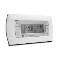
Il terminale remoto per µC
2
(MCH200TP* versione a pannello e MCH200TW* versione a parete) è un dispositivo elettronico che
permette il controllo a distanza di una unità di condizionamento gestita dal µC
2
. Le funzioni consentite sono le stesse ottenibili
dal display e dalla tastiera locale del µC
2
. La confezione comprende il terminale, l’alimentatore “RJ12 power supply” e il
cavo telefonico.
Montaggio a pannello (cod. MCH200TP00)
Questa versione è stata progettata per il montaggio a pannello, con dimensioni della dima di foratura pari a 127 x 69 mm e
2 fori circolari diametro 4 mm, come indicato in Fig. 1. Per l’installazione seguire le istruzioni riportate di seguito (Fig. A
1
):
• effettuare il collegamento del cavo telefonico;
• inserire il terminale, privo di cornice frontale, nel foro, e mediante le viti a testa svasata, fissare il dispositivo al pannello;
• infine, applicare la cornice a scatto.
Montaggio a parete (cod. MCH200TW00)
La versione per montaggio a parete del terminale prevede l’iniziale fissaggio del retrocontenitore A (Fig. B
1
), per mezzo di
una scatola standard a 3 moduli per interruttori.
• fissare il retrocontenitore alla scatola tramite le viti a testa bombata;
• effettuare il collegamento del cavo telefonico;
• appoggiare il frontale al retrocontenitore e fissare il tutto utilizzando le viti a testa svasata come illustrato in Fig. B
1
;
• infine, applicare la cornice a scatto.
Collegamenti elettrici (Fig. 3-4)
Collegare la linea seriale RS485 in uscita dall’alimentatore “RJ12 power supply” all’ingresso supervisore del µC
2
, utilizzando
un cavo schermato ad una coppia intrecciata. Alimentare i morsetti G-G0 con un trasformatore e un fusibile da 250 mAT,
come riportato nello schema di Fig. 3-4. Effettuare il collegamento tra l’alimentatore “RJ12 power supply” e il terminale
utilizzando il cavo telefonico (cod. S90CONN002 l = 80 cm) in dotazione. Nel caso la lunghezza sia insufficiente realizzare
un cavo telefonico pin-to-pin di lunghezza massima pari a 40 m.
Avvertenze:
• utilizzare esclusivamente un trasformatore di sicurezza;
• ai fini della sicurezza è obbligatorio inserire in serie al terminale ‘G’ un fusibile da 250 mA ritardato;
• se si utilizza un trasformatore unico per µC
2
e terminale rispettare la polarità G-G0 come da schema elettrico.
L’inversione equivale ad un cortocircuito sul secondario del trasformatore;
• non collegare a terra il secondario del trasformatore.
Linea alimentazione 24 Vac (G- G0) Linea seriale Rs485 verso µC
2
Distanze tipiche Sezione minima Velocità 19200 Baud
250 m 1,5 mm
2
(AWG16) Distanza massima RS485 1 km (con terminazione da 120 ohm)
100 m 0,5 mm
2
(AWG20) Caratteristiche cavo una coppia intrecciata + schermo
50 m 0,35 mm
2
(AWG22) Sezione AWG22
Tab. 1 Capacità per metro < 90 pF/m (ad esempio cavi
BELDEN 8761-8762)
Tab. 2
Installazione
Per rendere operativo il terminale remoto non è necessario effettuare alcuna configurazione del µC
2
in quanto il terminale
funziona qualsiasi sia l’indirizzo seriale impostato tramite il parametro H10. Assicurarsi però che il µC
2
sia dotato di interfaccia
seriale FCSER00000 (per versione guida DIN) oppure MCH2004850 (per versione a pannello).
Alla prima accensione comparirà sul display la versione firmware del µC
2
(Fig. A). Dopo circa 4 s
verrà visualizzata la maschera principale con i simboli che rappresentano lo stato del µC
2
(Fig. B).
Nel caso il collegamento RS485 non sia realizzato correttamente oppure il controllore sia spento, il
terminale cancellerà il contenuto del display e visualizzerà la scritta “OFFLINE” (Fig. C).
Modo Info
Le pressione contemporanea dei tasti “Up” + “Down” + “Sel” per più di 6 s, forza la
visualizzazione della maschera “INFO” (Fig. D) contenente informazioni sul sistema µC
2
e
sulla comunicazione.
Tramite la pressione del tasto “Prg” è possibile tornare alla maschera principale.
Informazioni visualizzate (Fig D):
Riga display Significato
1 Versione firmware terminale
2 Versione firmware µC
2
3 Indirizzo supervisore del µC
2
4 Tasso di errore percentuale relativo alla comunicazione tra terminale e µC
2
Tab. 3
Nel caso sia collegata la linea RS485 del supervisore tramite l’adattatore MCH200TSV0 ed il supervisore sia attivo, appare
in alto a destra l’icona “ ”; i due pallini a destra delle scritte Rx, Tx indicano rispettivamente i messaggi di richiesta
inviati dal supervisore al µC
2
di indirizzo H10 (Rx) e le trasmissioni di risposta da parte del µC
2
(Tx): pallino vuoto = nessuna
trasmissione (dati invariati), pallino pieno = dati trasmessi.
Collegamento alla rete di supervisione (MCH200TSV0)
Qualora si desideri collegare il µC
2
al terminale remoto MC2000TX00 senza perdere la connettibilità alla rete di supervisione,
è necessario installare l’adattatore seriale (opzionale) MCH200TSV0, come indicato in Fig. 2.
Disconnettere il connettore telefonico, aprire la finestrella che copre il pin-strip a 15 vie, utilizzando un tronchese appuntito,
inserire l’adattatore da pin-strip a plug 4 vie, rispettando il verso indicato in Fig 2 (pin 1 a sinistra dal lato del triangolo). Eseguire
il collegamento della rete RS485 al convertitore ed impostare il parametro H10 (indirizzo seriale) del µC
2
al valore desiderato.
Thank you for your choice. We trust you will be satisfied with your purchase.
The remote terminal for µC
2
(MCH200TP* panel version and MCH200TW* wall-mounting version), is an electronic device
that allows the remote control of an air-conditioning unit managed by the µC
2
. The functions allowed are the same as those
available on the display and the local keypad of the µC
2
. The packaging contains the remote terminal, “RJ12 power supply”
and telephone cable.
Panel installation (code MCH200TP00)
This version has been designed for panel installation, with the drilling template measuring 127 x 69 mm with 2 circular
holes, diameter 4 mm, as shown in Fig. 1. For installation proceed as follows (Fig. A
1
):
• connect the telephone cable;
• insert the terminal, without the front frame, in the opening, and use the countersunk screws to fasten the device to the panel;
• finally, apply the click-on frame.
Wall-mounting (code MCH200TW00)
The version of the terminal for wall-mounting requires the rear of the case A to be fastened (Fig. B
1
) using a standard
3-module switch box.
• fasten the rear of the case to the box using the round-head screws;
• connect the telephone cable;
• rest the front panel on the rear of the case and fasten the assembly using the countersunk screws, as shown in Fig. B
1
;
• finally, apply the click-on frame.
Electrical connections (Fig. 3-4)
Connect the RS485 serial line leaving the power supply “RJ12 power supply” to the supervisor input on the µC
2
, using a
twisted pair cable with shield. Power terminals G-G0 from a transformer with a 250 mAT fuse, as shown in the diagram in
Fig. 3-4. Make the connection between the power supply “RJ12 power supply” and the terminal using the telephone cable
(code S90CONN002 l = 80 cm) supplied. If the cable is not long enough, use a pin-to-pin telephone cable with a maximum
length of 40 m.
Warnings:
• only use safety transformers;
• for safety reasons a 250 mA slow-blow fuse must be fitted in series with terminal ‘G’;
• if using the same transformer for the µC
2
and the terminal, respect the polarity G-G0 as per the wiring diagram.
Reversing the polarity is the same as short-circuiting the secondary of the transformer;
• do not earth the secondary of the transformer.
24 Vac power supply line (G- G0) RS485 serial line to µC
2
Typical length Minimum cross-section Speed 19200 Baud
250 m 1.5 mm
2
(AWG16) Maximum RS485 distance 1 km (with 120 ohm terminals)
100 m 0.5 mm
2
(AWG20) Cable characteristics twisted pair + shield
50 m 0.35 mm
2
(AWG22) Cross-section AWG22
Tabl e 1 Capacitance per metre < 90 pF/m (for example, BELDEN
8761-8762 cables)
Tabl e 2
Installation
To install the remote terminal, no configuration is required on the µC
2
, as the terminal works with any serial address set for
parameter H10. Check, however, that the µC
2
is fitted with the serial interface FCSER00000 (DIN rail version) or
MCH2004850 (panel version). When first switched on the display will show the firmware version
of the µC
2
(Fig. A). After around 4s the main screen will be displayed, with the symbols that
represent the status of the µC
2
(Fig. B). In the event where the RS485 connection is not
performed correctly or the controller is off, the terminal will clear the display and show the
message “OFFLINE” (Fig. C).
Info mode
Pressing the “Up” + “Down” + “Sel” buttons together for more than 6 seconds displays the
“INFO” screen (Fig. D) containing information on the µC
2
system and on the communication.
Pressing the “Prg” button returns to the main screen.
Information displayed (Fig D):
Display row Meaning
1 Terminal firmware version
2µC
2
firmware version
3 Supervisor address of the µC
2
4 Percentage error rate in the communication between the terminal and µC
2
Table 3
If the RS485 supervisor line is connected via the MCH200TSV0 adapter and the supervisor is active, the “ ” icon is
displayed at the top right; the two circles to the right of the Rx, Tx fields indicate respectively the request messages sent by
the supervisor to the µC
2
with address H10 (Rx) and the response from the µC
2
(Tx): empty circle = no data sent (data
unchanged), full circle = data sent.
Connection to the supervisor network (MCH200TSV0)
To connect the µC
2
to the remote terminal MC2000TX00 while still maintaining the possibility to connect to the supervisor
network, the serial adapter (optional) MCH200TSV0 must be used, as shown in Fig. 2.
Disconnect the telephone connector, open the cover on the 15-way pin strip using a small pair of wire cutters, and insert
the adapter (pin-strip to 4-pin plug), in the direction shown in Fig 2 (pin 1 on the left from the side of the triangle). Connect
the RS485 network to the converter and set the parameter H10 (serial address) of the µC
2
to the desired value.
cod. +050001065 - rel. 2.0 - 09/06/2004
MCH200TP00/MCH200TW00:
Terminale remoto per µC
2
/
Remote terminal for µC
2
Dimensioni /
Dimensions
Fig. 1
Collegamento alla rete di supervisione /
Connection to the supervisor network:
Fig. 2
Fig. A
Terminale versione da pannello
Panel mounting terminal