pCO Sistema
Code: +030220336 - rel. 1.5 - 22/12/10
37
4.4.3
4.4.34.4.3
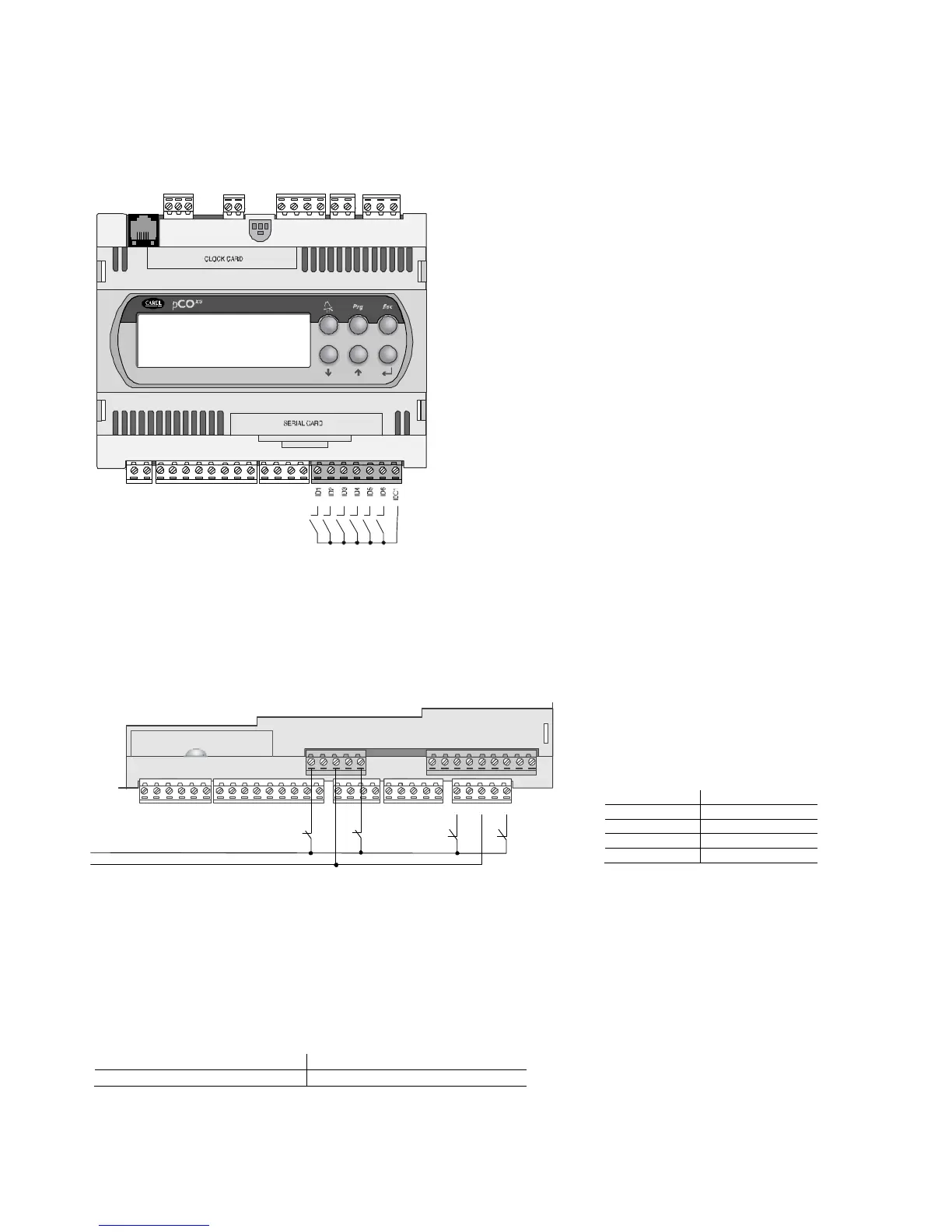
4.4.3 Connecting the digital inputs to the pCO
Connecting the digital inputs to the pCOConnecting the digital inputs to the pCO
Connecting the digital inputs to the pCOXS
XSXS
XS
The pCO
XS
features up to 6 not optoisolated digital inputs, with voltage-free contacts, for connection to safety devices, alarms, device status indictors and remote control
signals, etc.
These operate at 24 Vdc (supplied by the pCO
XS
) with a guaranteed current at the contact of 6 mA.
Warning:
Warning: Warning:
Warning: separate as much as possible the probe and digital input signal cables from the cables carrying inductive loads and power cables to avoid possible
electromagnetic disturbance.
The following figure shows the diagram for connecting the digital inputs.
4.4.4
4.4.44.4.4
4.4.4 230 Vac digital input
230 Vac digital input230 Vac digital input
230 Vac digital inputs
ss
s
FOR PCO
FOR PCOFOR PCO
FOR PCO
3
33
3
, PCO
, PCO, PCO
, PCO
1
11
1
AND PCO
AND PCOAND PCO
AND PCO
C
CC
C
ONLY
ONLYONLY
ONLY
There are up to two groups of 230 Vac inputs. Each group features two inputs and the groups have double insulation between them and therefore may have different
reference voltages. The digital inputs cannot be independent within each group: for example, with reference to Fig. 4.m, inputs ID15 and ID16, due to the common
terminal, must be powered at the same voltage to avoid dangerous short-circuits and/or 230 Vac being supplied to circuits operating at lower voltages. In any case the
inputs have double insulation from the rest of the controller.
The following figure represents one of the most common diagrams for connecting the 230 Vac digital inputs.
The uncertainty of the switching threshold ranges from 43
to 90 Vac. It is recommended to use a 100 mA fuse in series
with the digital inputs.
Tab. 4.i
Tab. 4.iTab. 4.i
Tab. 4.i
Warnings for the 230 Vac digital inputs
Warnings for the 230 Vac digital inputsWarnings for the 230 Vac digital inputs
Warnings for the 230 Vac digital inputs:
• 230 Vac 50/60 Hz +10/-15 %;
• for each group, the two inputs, 24 Vac/Vdc or 230 Vac have the same common pole, the inputs will both work at the same voltage (24 Vac/Vdc or 230 Vac).
Insulation is primary.
4.4.5
4.4.54.4.5
4.4.5 Distance of the digital inputs
Distance of the digital inputsDistance of the digital inputs
Distance of the digital inputs
Important note
Important noteImportant note
Important note: do not connect other devices to the digital inputs.
The sizes of the cables used for connecting the digital inputs over a distance are shown in the following table:
size (mm
size (mmsize (mm
size (mm
) for length up to 00 m
) for length up to 00 m) for length up to 00 m
) for length up to 00 m
0.25 0.5
If the product is installed in industrial environments (application of the EN 61000-6-2 standard) the length of the connections must be less than 30m.
In any case, this length should not be exceeded so as to prevent reading errors.
J4
built-in terminal
Fig. 4.l
Fig. 4.lFig. 4.l
Fig. 4.l
ID15H
ID15
IDC15
ID16
ID16H
Y5
Y6
ID17
ID18
IDC17
B9
BC9
B10
BC10
Serial Card
 Loading...


