Standard Shelter
Cod. +030221471 – Rel. 2.0 – April 01, 2003
29
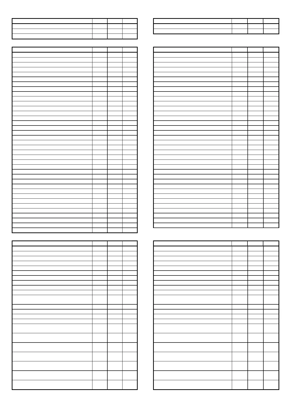
DESCRIPTION SCR. ADD. TYPE DESCRIPTION SCR. ADD. TYPE
Driver 2 alarm, probes faulty or disconnected
AL42
65 R
Driver 2 EEPROM faulty or damaged
AL43
66 R
Driver 2 valve motor faulty or damaged
AL44
67 R
16.5.2 ANALOGUE VARIABLES
DESCRIPTION SCR. ADD. TYPE DESCRIPTION SCR. ADD. TYPE
Pressure probe 1 reading I0 1 R Cond. 2 pressure probe calibration A8 38 R/W
Humidity probe reading I0 2 R Cond. 1 temperature probe calibration Aa 39 R/W
Room temperature probe reading I1 3 R Cond. 2 temperature probe calibration Aa 40 R/W
Outside temperature probe reading I1 4 R Maximum value pressure probe 1 C9 41 R/W
Air outlet temperature probe reading I1 5 R Minimum value pressure probe 1 C9 42 R/W
Pressure probe 2 reading I0 6 R Maximum value pressure probe 2 Ca 43 R/W
Cond. 1 temperature probe reading I0 7 R Minimum value pressure probe 2 Ca 44 R/W
Cond. 2 temperature probe reading I0 8 R Maximum value humidity probe Cc 45 R/W
Temperature set point S0 9 R/W Minimum value humidity probe Cc 46 R/W
Minimum temperature set point limit P1 10 R/W % of band for min. freecool. opening G2 47 R/W
Maximum temperature set point limit P1 11 R/W % of band for max. freecool. opening G2 48 R/W
Humidity set point S0 12 R/W Minimum freecooling open G2 49 R/W
Minimum humidity set point limit P2 13 R/W Minimum outlet fan speed G3 50 R/W
Maximum humidity set point limit P2 14 R/W Maximum outlet fan speed G3 51 R/W
Freecooling opening I8 15 R Outlet fan speed in dehumid. G3 52 R/W
Outlet fan speed I8 16 R Stop dehumidification temp. differential G4 53 R/W
Condenser 1 fan speed I9 17 R Restart dehumidification temp. offset G4 54 R/W
Condenser 2 fan speed I9 18 R High pressure alarm set point G5 55 R/W
Temperature dead zone P3 19 R/W High pressure alarm differential G5 56 R/W
Proportional band in Cooling P3 20 R/W Condensing (pressure) set point G6 57 R/W
Proportional band in Heating P3 21 R/W Condensing (pressure) differential G6 58 R/W
Proportional band in Humidification P4 22 R/W Condensing (temperature) set point G7 59 R/W
Proportional band in Dehumidification P4 23 R/W Condensing (temperature) differential G7 60 R/W
Freecooling offset P5 24 R/W Max. condenser fan speed G8 61 R/W
Minimum humidity limit for freecooling P6 25 R/W Min. condenser fan speed G8 62 R/W
Maximum humidity limit for freecooling P6 26 R/W Prevent set point (pressure) G9 63 R/W
High ambient temperature alarm offset P8 27 R/W Prevent differential (pressure) G9 64 R/W
Low ambient temperature alarm offset P8 28 R/W Prevent set point (temperature) Ga 65 R/W
High ambient humidity alarm offset P9 29 R/W Prevent differential (temperature) Ga 66 R/W
Low ambient humidity alarm offset P9 30 R/W Unit in standby ON for low temperature - differential Gd 67 R/W
Outlet limitation set point Pa 31 R/W Unit in standby OFF for low temperature - offset Gd 68 R/W
Outlet limitation differential Pa 32 R/W Unit in standby ON for high temperature - differential Ge 69 R/W
Cond. 1 pressure probe calibration A8 33 R/W Unit in standby OFF for high temperature - offset Ge 70 R/W
Humidity probe calibration A8 34 R/W
Room temperature probe calibration A9 35 R/W
Outside temperature probe calibration A9 36 R/W
Outlet temperature probe calibration A9 37 R/W
16.5.3 INTEGER VARIABLES
DESCRIPTION SCR. ADD. TYPE DESCRIPTION SCR. ADD. TYPE
Current hours K0 1 R Type AL8 (0=serious;1=min.1;2=min.2) Pb 62 R/W
Current minutes K0 2 R Type AL9 (0=serious;1=min.1;2=min.2) Pb 63 R/W
Day K0 3 R Type AL10 (0=serious;1=min.1;2=min.2) Pb 64 R/W
Month K0 4 R Type AL11 (0=serious;1=min.1;2=min.2) Pb 65 R/W
Year K0 5 R Type AL12 (0=serious;1=min.1;2=min.2) Pb 66 R/W
Hour setting K0 6 R Type AL13 (0=serious;1=min.1;2=min.2) Pb 67 R/W
Minute setting K0 7 R/W Type AL14 (0=serious;1=min.1;2=min.2) Pb 68 R/W
Day setting K0 8 R/W Type AL15 (0=serious;1=min.1;2=min.2) Pb 69 R/W
Month setting K0 9 R/W Type AL16 (0=serious;1=min.1;2=min.2) Pb 70 R/W
Year setting K0 10 R/W Type AL17 (0=serious;1=min.1;2=min.2) Pb 71 R/W
Select refrigerant (0=no; 1=R22; 2=134a;
3=404a; 4=407C; 5=410A)
C1 11 R/W Type AL18 (0=serious;1=min.1;2=min.2) Pb 72 R/W
Number of compressors C3 12 R/W Type AL19 (0=serious;1=min.1;2=min.2) Pb 73 R/W
Number of heaters C3 13 R/W Type AL20 (0=serious;1=min.1;2=min.2) Pb 74 R/W
Number of compressors for dehumidification C3 14 R/W Type AL21 (0=serious;1=min.1;2=min.2) Pc 75 R/W
Number of condenser fans C5 15 R/W Type AL22 (0=serious;1=min.1;2=min.2) Pc 76 R/W
Type of signal from pressure probe 1 (2=0-1V;
3=0-10V; 4=current)
C9 16 R/W Type AL23 (0=serious;1=min.1;2=min.2) Pc 77 R/W
Type of signal from pressure probe 2 (2=0-1V;
3=0-10V; 4=current)
Ca 17 R/W Type AL24 (0=serious;1=min.1;2=min.2) Pc 78 R/W
Type of signal, condens. 1 T probe (0=NTC;
1=PT1000; 2=0-1V; 3=0-10V; 4=current)
Cb 18 R/W Type AL25 (0=serious;1=min.1;2=min.2) Pc 79 R/W
Type of signal, condens. 2 T probe (0=NTC;
1=PT1000; 2=0-1V; 3=0-10V; 4=current)
Cb 19 R/W Type AL26 (0=serious;1=min.1;2=min.2) Pc 80 R/W
Type of signal from humidity probe (2=0-1V;
3=0-10V; 4=current)
Cc 20 R/W Type AL27 (0=serious;1=min.1;2=min.2) Pc 81 R/W
Type of signal from room temperature probe
(0=NTC; 1=PT1000)
Cd 21 R/W Type AL28 (0=serious;1=min.1;2=min.2) Pc 82 R/W
Type of signal from outlet temperature probe
(0=NTC; 1=PT1000)
Cd 22 R/W Type AL29 (0=serious;1=min.1;2=min.2) Pc 83 R/W
 Loading...


