Analog inputs
analog conversion 10 bit A/D converter, built-in CPU
type passive: Carel NTC temp. probe, (-50/90°C;R/T 10kΩ at 25°C), PT1000 (-100÷200°C; R/T 1000Ω at 0°C)
or free digital input (5mA), selected via software (B4, B5, B9, B10 inputs)
universal:Carel NTC temp.probe (see passive type), voltage:0/1Vdc or 0/10Vdc>;
current: 0/20mA or 4/20mA, selected via software (B1, B2, B3, B6, B7,B8 inputs)
input resistance in 0/20mA = 50Ω.
max.number 5, 8, 10, on SMALL, MEDIUM, LARGE boards respectively
time constant for each input 0.5s
WARNING: for powering any active probe it is possible to use the 21Vdc at +Vdc terminal; the max. current that can be delivered is 200mA
thermally protected against short circuits. Differently from pCO
B
, the input under voltage 0/1Vdc is operative only for the positive values
and not for -0,5/1Vdc (it is not possible to use Carel standard temperature probes, set for the signal 0/1V, because they includes external
signals at 0/1V so use 4/20mA or NTC).
Digital inputs
type optically insulated
max.number 8, 14, 18 on SMALL, MEDIUM, LARGE boards respectively according to the combinations shown below:
No.of optically insulated inputs at No.of optically insulated inputs at total inputs
24 Vac 50/60 Hz o 24 Vdc 24 Vac/Vdc o 230 Vac (50/60 Hz)
SMALL 8 none 8
MEDIUM 8 + 4 2 14
LARGE 8 + 4 + 2 2 + 2 18
WARNING: - 230Vac 50/60Hz (+10%, -15%)
- the two 230/24Vac inputs have the same common pole, so they both will be at 24Vac or 230Vac
Main insulation.
- in case of Vdc inputs connect the negative pole to the common terminal.
Note: please keep probe and digital input leads as far as possible from power cables to avoid possible electromagnetic noise.
Analog outputs
type 0/10Vdc optically insulated
max.number 4, 4, 6, on SMALL, MEDIUM, LARGE boards respectively
power external 24Vac/Vdc
resolution 8 bit
max.load 1kΩ (10mA)
Digital outputs
type relay
max.number 8, 13, 18, on SMALL, MEDIUM, LARGE boards respectively
They are grouped in 3 with two common pole terminals in order to assemble the common poles easily. Be careful to the current flowing in
common terminals, because it must not exceed the rated current of each single terminal, that is: 8A resistive for removable-screw
terminals.The relays are divided into groups, according to the insulating distance.Inside each group the relays have their single main
insulation, so they must be exposed to the same voltage (in general 24Vac or 230Vac).Among the groups there is double-insulation,
therefore the groups can be of different voltage.
Anyway the double-insulation does exist toward the rest of the controller.
groups 1, 2, 3, 4, 5, 6, 7 - 8 (alarm relay) - 9, 10, 11, 12, 13 - 14, 15 - 16, 17, 18.
switch contacts 1, 3, 5, on SMALL, MEDIUM, LARGE boards respectively
commutable power 2000VA, 250Vac, 8A resistives, 2A FLA, 12A LRA according to UL873 (30,000 cycles)
2A resistives, 2A inductives, cos
ϕ
= 0,4, 2(2)A according to EN 60730-1 (100,000 cycles)
Connection to user terminal
type asynchronous 2-lead half duplex dedicated
connector for teminal 6-way telephone-type
connector for pLAN 3-way plug-in connector
driver CMR 7V balanced differential (type RS485)
Max.allowable terminal unit-main board distances (or between the two most far devices connected in pLAN) are listed below:
with telephone-type cable with AWG24 shielded cable
cable resistance (Ω/m) max distance (m) cable resistance (Ω/m) max distance (m)
≤ 0.14 600 ≤0.078 600
≤ 0.25 400
Other specifications
storage conditions -20T70, 90%r.H.non-condensing
operating conditions -10T60, 90%r.H.non-condensing
index of protection IP20, IP40 (front panel only)
environmental pollution normal
Classification according to protection against electric shock should be integrated into Class 1 and/or 2 devices
PTI of insulating materials 250V
period of electric stress across insulating parts long
type of actions 1C
type of disconnection or microinterruption microinterruption
category of resistance to heat and fire D (UL94 - V0)
immunity against voltage surges category 1
ageing period (operating hours) 80,000
no. of automatic operating cycles (e.g.:relay) 100,000 (EN 60730-1); 30,000 (UL873)
software Class and structure Class A
device is not intended to be and hand-held
According to the limits quoted on the Safety Standards relevant to electromagnetic compatibility (see conformity declaration published on
the installation manual), rare malfunctioning is founded only on display and LED indications. LEDs and display are restored when the
disturb ends.
Warning: for applications subject to strong vibrations (1,5mm pk-pk 10/55Hz), we suggest you to fasten, through fastening clamps, the
cables connected to the pCO
2
at about 3cm of distance from the connectrors.
Carel si riserva la possibilità di apportare modifiche o cambiamenti ai propri prodotti senza alcun preavviso./ Carel reserves the right to alter the features of its products without prior notice.
CAREL S.p.A.
Via dell’Industria, 11 - 35020 Brugine - Padova (Italy)
Tel.(+39) 0499716611 – Fax (+39) 0499716600
http://www.carel.com – e-mail: carel@carel.com
cod. +050003560 rel. 1.0 - 23.10.02
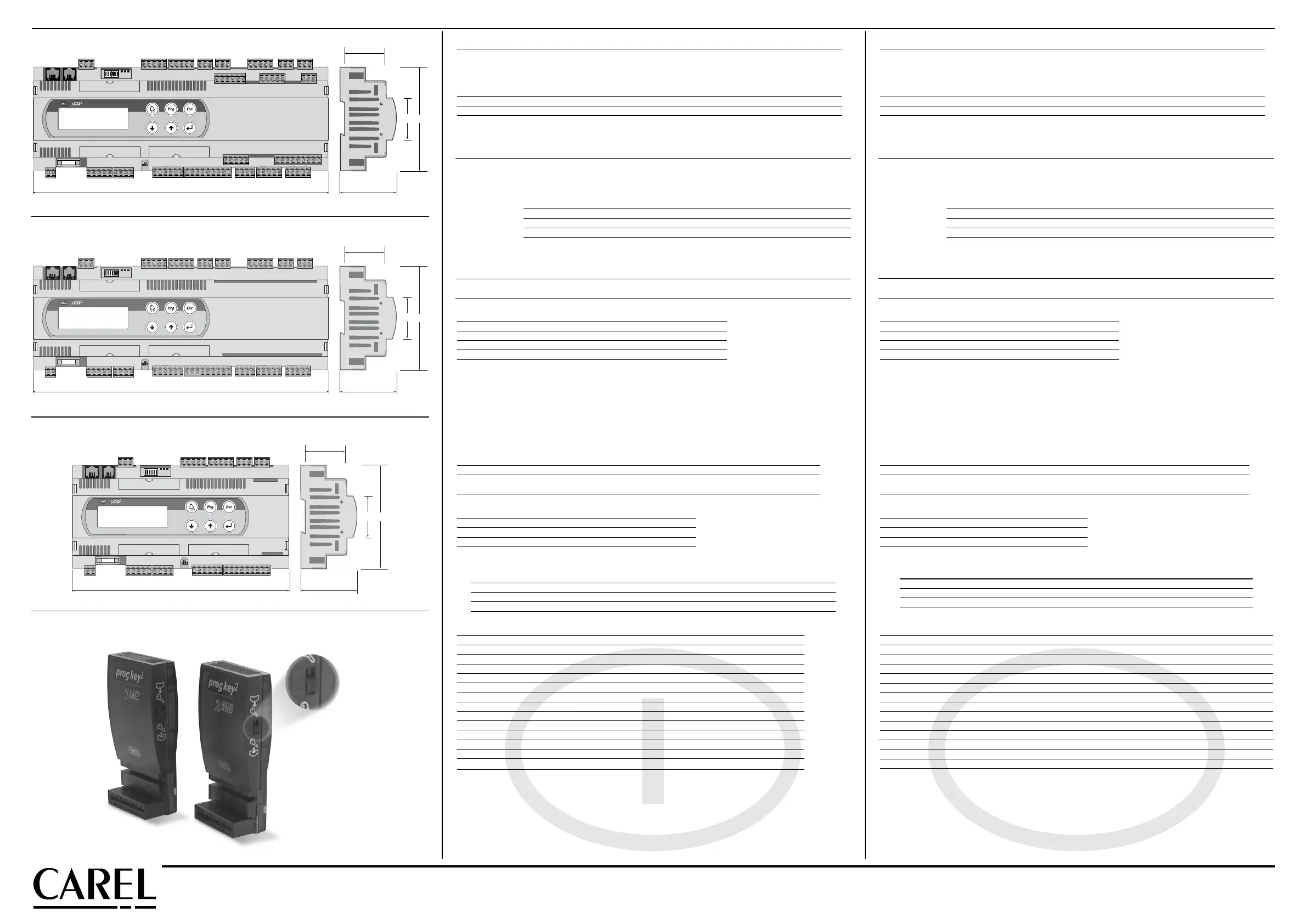
pCO
2
versione LARGE / pCO
2
LARGE model
pCO
2
versione MEDIUM / pCO
2
MEDIUM model
pCO
2
versione SMALL / pCO
2
SMALL model
Chiavi / Key
Fig. 2
Fig. 3
Fig. 4
Ingressi analogici
conversione analogica A/D converter a 10 bit CPU built-in
tipo passivo:sensore di temp. NTC Carel, (-50/90 °C; R/T 10 kΩ a 25 °C), PT1000 (-100/200 °C; R/T
1000 Ω a 0°C) o input digitale pulito (5 mA), selezionabili via software (ingressi B4, B5, B9, B10)
universale: sensore di temp.NTC Carel (vedi tipo passivo), tensione: 0/1 Vdc o 0/10 Vdc,
corrente: 0/20 mA o 4/20 mA, selezionabili via software (ingressi B1, B2, B3, B6, B7, B8)
resistenza di ingresso in 0/20 mA= 50Ω
numero massimo 5, 8, 10, rispettivamente sulle schede SMALL, MEDIUM, LARGE
cost. di tempo per ogni ingresso 0,5 s
AVVERTENZA: l’alimentazione di eventuali sonde attive, è possibile utilizzare i 21 Vdc disponibili sul morsetto +Vdc, la corrente massima
erogabile è di 200 mA protetta termicamente contro i corti circuiti. A differenza del pCO
B
l’ingresso in tensione 0/1 Vdc vale solo per valori
positivi e non per -0,5/1 Vdc (non sono quindi utilizzabili le sonde di temperatura standard Carel, configurate per il segnale 0/1V, perchè
comprendono segnali esterni al 0/1V, usare quindi 4/20mA o NTC).
Ingressi digitali
tipo optoisolati
numero massimo 8, 14, 18, rispettivamente sulle schede: SMALL, MEDIUM, LARGE, secondo le combinazioni riportate qui sotto:
numero ingressi optoisolati a numero ingressi optoisolati a totale ingressi
24 Vac 50/60 Hz o 24 Vdc 24 Vac/Vdc o 230 Vac (50/60 Hz)
SMALL 8 nessuno 8
MEDIUM 8 + 4 2 14
LARGE 8 + 4 + 2 2 + 2 18
AVVERTENZE: - 230 Vac 50/60 Hz (+10%, -15%)
- i due ingressi a 230/24 Vac, hanno il medesimo polo comune e quindi saranno entrambi a 24Vac/Vdc o 230 Vac.
L’ isolamento è principale.
- in caso di ingressi in continua (Vdc) collegare il polo negativo al morsetto comune.
Nota: separare quanto più possibile i cavi dei segnali delle sonde e degli ingressi digitali dai cavi relativi ai carichi induttivi e di potenza,
per evitare possibili disturbi elettromagnetici.
Uscite analogiche
tipo 0/10 Vdc optoisolate
numero massimo 4, 4, 6, rispettivamente sulle schede: SMALL, MEDIUM, LARGE
alimentazione esterna 24 Vac/Vdc
risoluzione 8 bit
carico massimo 1 kΩ (10 mA)
Uscite digitali
tipo relè
numero massimo 8, 13, 18, rispettivamente sulle schede: SMALL, MEDIUM, LARGE
Sono raggruppate a 3 con due morsetti di polo comune per un facile assemblaggio dei poli comuni. Prestare attenzione alla corrente
circolante nei morsetti comuni in quanto la stessa non deve superare la corrente nominale di un singolo morsetto, ovvero:8 A per i
morsetti estraibili. I relè sono divisi in gruppi, a seconda della distanza di isolamento. All’interno di un gruppo, i relè hanno tra loro
isolamento principale e quindi devono essere sottoposti alla medesima tensione (generalmente 24 Vac o 230 Vac).Tra i gruppi c’è il
doppio isolamento quindi i gruppi possono essere a tensione diversa.
In ogni caso verso il resto del controllo, esiste il doppio isolamento.
Gruppi 1, 2, 3, 4, 5, 6, 7 - 8 (relè di allarme) - 9, 10, 11, 12, 13 - 14, 15 - 16, 17, 18.
Contatti in scambio 1, 3, 5, ripettivamente sulle schede: SMALL, MEDIUM, LARGE
Potenza commutabile 2000 VA, 250 Vac, 8 A resistivi, 2 A FLA, 12 A LRA secondo UL873 (30.000 cicli)
2 A resistivi, 2 A induttivi, cosϕ=0,4, 2(2) A secondo EN 60730-1 (100.000 cicli)
Collegamento al terminale utente
tipo asincrono half duplex a 2 fili dedicato
connettore per terminale tipo telefonico 6 vie
connettore per pLAN connettore estraibile 3 vie
driver differenziale bilanciato CMR 7 V (tipo RS485)
Le distanze massime ammesse tra terminale e scheda base (oppure tra i due dispositivi più lontani connessi in pLAN) sono quelle
riportate nella seguenta tabella:
con cavo telefonico con cavo schermato AWG24
resistenza del cavo (Ω/m) distanza massima (m) resistenza del cavo (Ω/m) distanza massima (m)
≤ 0,14 600 ≤0,078 600
≤ 0,25 400
Altre caratteristiche
condizioni di immagazzinamento -20T70, 90% UR non condensante
condizioni di funzionamento -10T60, 90% UR non condensante
grado di protezione IP20, IP40 nel solo frontalino
inquinamento ambientale normale
classe secondo la protezione contro le scosse elettriche da integrare su apparecchiature di Classe I e/o II
PTI dei materiali per isolamento 250 V
periodo delle sollecitazioni elettriche delle parti isolanti lungo
tipo azioni 1C
tipo disconnessione o microinterruzione microinterruzione
categoria di resistenza al calore e al fuoco categoria D (UL94 - V0)
immunità contro le sovratensioni categoria 1
caratteristiche di invecchiamento (ore di funzionamento) 80.000
n. cicli di manovra operazioni automatiche 100.000 (EN 60730-1); 30.000 (UL 873)
classe e struttura del software Classe A
il dispositivo non è destinato ad essere tenuto in mano
Nel rispetto dei limiti imposti dalle Normative di sicurezza sulla compatibilità elettromagnetica richiamate nella dichiarazione di conformità
(vedi manuale di installazione), gli unici e sporadici malfunzionamenti riscontrati riguardano le indicazioni del display e dei LED. Display e
LED si autoripristinano al cessare del disturbo.
Avvertenza: per applicazioni soggette a forte vibrazioni (1,5 mm pk-pk 10/55 Hz) si consiglia di fissare tramite fascette i cavi collegati al
pCO
2
a circa 3 cm di distanza dai connettori.
Fig. 5
 Loading...


