EasyManua.ls Logo

Carel pLDPRO PLD GFP00 Series - User Manual

Carel pLDPRO PLD GFP00 Series
2 pages
Print Icon
To Next Page IconTo Next Page
Loading...
+050001840 - rel. 1.2 - 16.12.2013
PLD**GFP00 Interfaccia utente / User interface
pLDPRO
Il display grafi co pLDPRO è un dispositivo elettronico,
compatibile con i precedenti terminali della linea PGD1,
che consente la completa gestione della grafi ca tramite la
visualizzazione di icone (defi nite a livello di sviluppo software
applicativo) e la gestione di font internazionali di due
dimensioni: 6x8 e 12x16 pixels e segnale acustico attivabile
da buzzer. Il software applicativo è residente soltanto sulla
scheda pCO, il terminale non ha bisogno di nessun software
aggiuntivo in fase di utilizzo. Inoltre il terminale off re un ampio
range di temperatura di funzionamento (-20T60 °C) e il frontale
garantisce un elevato grado di protezione (IP65).
Installazione pLDPRO
Questo terminale è stato progettato per il montaggio a
pannello; la dima di foratura deve avere dimensioni di
71x29mm come indicato in Fig. 1. Per l’installazione seguire le
istruzioni riportate di seguito:
Inserire il terminale nell’apertura, e fi ssare il dispositivo al
pannello utilizzando due staff e di plastica scorrevoli laterali,
come mostrato in Fig.2.
Infi ne, installare la cornice a scatto.
Connessioni elettriche
Collegare il cavo telefonico (cod. S90CONN00 *) dal controllo
pCO al connettore (RJ11) posto sul retro del terminale. Come
indicato in Fig.3
Con gurazione indirizzo
È possibile confi gurare l’indirizzo del terminale solo dopo aver
fornito alimentazione allo stesso tramite il connettore telefonico
RJ11 (il valore preimpostato in fabbrica è 32). Per entrare in
modalità confi gurazione premere contemporaneamente i tasti
++e (sempre presenti in tutte le versioni) per almeno
5 secondi; verrà visualizzata la maschera di Fig. 4 con il cursore
lampeggiante nell’angolo in alto a sinistra:
Per modifi care l’indirizzo del terminale (display address
setting) premere una volta il tasto : il cursore si sposterà sul
campo indirizzo (nn).
Tramite i tasti ↓↑selezionare il valore voluto, e confermare
ripremendo il tasto . Se il valore selezionato è diverso da
quello memorizzato precedentemente apparirà la maschera
di Fig. 5 e il nuovo valore verrà memorizzato nella memoria
permanente del display.
Se si imposta il campo nn al valore 0, il terminale comunicherà
con la scheda pCO usando il protocollo punto-punto (non
pLAN) e il campo “I/O Board address: xx” scompare in quanto
privo di signifi cato.
pCO: assegnazione lista terminali privati e
condivisi (per modalità pLAN)
A questo punto, se fosse necessario modifi care la lista dei
terminali associata ad ogni singola scheda pCO, si dovrà
seguire la seguente procedura:
entrare nella modalità confi gurazione con i tasti
++, come descritto nel paragrafo precedente;
premere il tasto no a che il cursore si posiziona sul
campo xx (I/O board address) Fig. 4;
tramite i tasti ↓↑scegliere l’indirizzo della scheda pCO
desiderata. I valori selezionabili saranno solo quelli delle
schede pCO eff ettivamente in linea. Se la rete pLAN non
funziona correttamente, oppure non è presente nessuna
scheda pCO, non sarà possibile modifi care il campo che
mostrerà solo “—”;
premendo ancora una volta il tasto verranno visualizzate
in sequenza le maschere di Fig. 5;
anche qui il tasto muove il cursore da un campo all’altro e i
tasti ↓↑ cambiano il valore del campo corrente. Il campo
P:xx mostra l’indirizzo della scheda selezionata; nell’esempio
di fi gura è stata selezionata la 12;
per uscire dalla procedura di confi gurazione e memorizzare i
dati selezionare il campo “OK ?” impostare Yes e confermare
con il tasto .
I campi della colonna Adr rappresentano gli indirizzi dei
terminali associati alla scheda pCO di indirizzo 12, mentre la
colonna Priv/Shared indica il tipo di terminale.
Nota: i terminali della linea pLDPRO non possono essere
confi gurati come “Sp (shared printer) in quanto privi dell’uscita
stampante. Se il terminale rimane inattivo (nessun tasto
premuto) per più di 30 secondi esce automaticamente dalla
procedura di confi gurazione senza memorizzare gli eventuali
cambiamenti.
drilling template
71x29 mm
76 mm
34.6 mm
38.4 mm
34.4 mm
Dimensioni / Dimensions (mm)
Montaggio a pannello /
Panel mounting terminal
pLAN
Fig. 2
Fig. 3
The pLDPRO graphic display is an electronic device that is
compatible with the previous PGD1 line terminals; it allows
complete management of graphics by the display of icons
(defi ned at application software development level), and
the management of international fonts, in two sizes: 6x8 and
12x16 pixels, and acoustic signal through piezoelectric buzzer
as well. The application software resides on the pCO controller
and therefore the terminal does not require any additional
software for operation. Furthermore, the terminals feature a
wide operating temperature range (-20T60 °C) , the index of
protection of front panel of IP65.
pLDPRO Installation
This terminal has been designed for panel installation; the
drilling template measures 71x29mm, as shown in Fig.1. For
installation, proceed as follows:
Insert the terminal into the opening, and fasten the device
to the panel using two lateral sliding plastic brackets, as
shown in Fig.2.
Finally, fi t the click-on frame
Electrical connection
pLAN: Connect the telephone cable (code S90CONN00*)
from the pCO controller to the connector provided (RJ11)
on the rear of the terminal. As shown in Fig.3
Con guring the address
The address of the terminal can be confi gured only after
having connected the power supply, using the RJ11 telephone
jack (the factory default value is 32).
To access confi guration mode, press the
++buttons
together and hold them for at least 5 seconds; the screen
shown in Fig. 4 will be displayed, with the cursor fl ashing in
the top left corner:
• To change the address of the terminal (display address
setting), press the button once, the cursor will move to
the address fi eld (nn).
• Use the ↓↑ buttons to select the desired value, and
confi rm by pressing again. If the value selected is not the
same as the one saved previously, the screen shown in Fig.
5 will be displayed, and the new value will be saved to the
permanent memory.
If the fi eld nn is set to 0, the terminal will communicate with
the pCO controller using “point-to-point” protocol (not pLAN)
and the fi eld “I/O Board address: xx” will not be displayed, as it
has no meaning.
pCO: assigning the list of private and shared
terminals (For pLAN mode)
At this point, if the list of terminals associated with each
individual pCO controller needs to be modifi ed, proceed as
follows:
access confi guration mode using the
++ buttons,
as described in the previous paragraph;
• press the button until the cursor moves to the fi eld xx (I/O
board address) Fig.4;
• use the ↓↑buttons to select the pCO controller in question.
The values available correspond to the pCO controllers that
are eff ectively on line. If the pLAN network is not working
correctly, or if no pCO controller is present, the fi eld cannot
be modifi ed, and the symbol “—” will be displayed;
• pressing again displays the screens shown in Fig. 6, in
sequence;
here too, the button moves the cursor from one fi eld
to the next, and the ↓↑ buttons change the value of
the current fi eld. The fi eld P:xx shows the address of the
controller selected; in the example shown in the fi gure, the
value 12 has been selected;
to exit the confi guration procedure and save the data, select
the fi eld “OK ?”, choose Yes and confi rm by pressing .
The fi elds in the Adr” column represent the addresses of
the terminals associated with the pCO controller that has
address 12, while the Priv/Shared column indicates the type
of terminal.
Note: the pLDPRO terminals cannot be confi gured as “Sp
(shared printer), as they have no printer port.
If the terminal remains inactive (no button is pressed) for
more than 30 seconds, the confi guration procedure is exited
automatically, without saving any changes.
Fig. 1
Connessioni elettriche /
Electrical connection
Smaltimento del prodotto: l’apparecchiatura (o il
prodotto) deve essere oggetto di raccolta separata in
conformità alle vigenti normative locali in materia di
smaltimento. /
Disposal of the product: the appliance (or
the product) must be disposed of separately in accordance
with the local waste disposal legislation in force.
Question and Answer IconNeed help?

Do you have a question about the Carel pLDPRO PLD GFP00 Series and is the answer not in the manual?

Overview

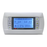
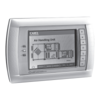
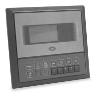
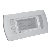
The CAREL PLDPRO graphic display is an electronic device designed for panel installation, compatible with previous PGD1 line terminals. It facilitates comprehensive graphic management through the display of icons (defined at the application software development level) and supports international fonts in two sizes: 6x8 and 12x16 pixels. Additionally, it features an acoustic signal generated by a piezoelectric buzzer. The application software resides solely on the pCO controller, eliminating the need for additional software on the terminal itself during operation. The terminal operates within a wide temperature range of -20°C to 60°C, and its front panel boasts an IP65 protection rating.

Installation:

The PLDPRO terminal is designed for panel mounting. The drilling template requires dimensions of 71x29mm. To install, insert the terminal into the opening, secure it to the panel using two lateral sliding plastic brackets, and then fit the click-on frame.

Electrical Connection:

For pLAN mode, connect the telephone cable (code S90CONN00*) from the pCO controller to the RJ11 connector located on the rear of the terminal.

Configuration:

Address Configuration:

The terminal's address can only be configured after connecting the power supply via the RJ11 telephone jack. The factory default address is 32. To enter configuration mode, press and hold the ◉ + + + ↑ buttons simultaneously for at least 5 seconds. A screen will appear with a flashing cursor in the top left corner. To change the display address setting, press the button once to move the cursor to the address field (nn). Use the ↓↑ buttons to select the desired value and confirm by pressing again. If the selected value differs from the previously saved one, the new value will be stored in the permanent memory. If the 'nn' field is set to 0, the terminal will communicate with the pCO controller using a "point-to-point" protocol (not pLAN), and the "I/O Board address: xx" field will not be displayed.

pCO: Assigning Private and Shared Terminals (for pLAN mode):

To modify the list of terminals associated with each pCO controller:

  1. Access configuration mode using the ◉ + + + ↑ buttons.
  2. Press the button until the cursor moves to the 'xx' field (I/O board address).
  3. Use the ↓↑ buttons to select the desired pCO controller. Only pCO controllers currently online will be available. If the pLAN network is not functioning or no pCO controller is present, the field will display "-".
  4. Pressing again will display subsequent screens.
  5. The button moves the cursor between fields, and the ↓↑ buttons change the current field's value. The 'P:xx' field shows the selected controller's address (e.g., 12 in the example).
  6. To exit and save, select "OK?", choose "Yes", and confirm by pressing . The 'Adr' column shows terminal addresses associated with the pCO controller (address 12 in the example), while 'Priv/Shared' indicates the terminal type. Note: PLDPRO terminals cannot be configured as "Sp" (shared printer) as they lack a printer port. If inactive for over 30 seconds, the configuration procedure exits automatically without saving changes.

Fault Signals:

If the terminal detects an offline pCO controller, it displays "I/O Board xx fault." If no network signal is received, it displays "NO LINK."

Displaying Network Status and Firmware Release:

Pressing and holding the ◉ + + + ↑ buttons for at least 10 seconds displays the network status and firmware version screen. This screen shows the pLAN network status, including connected devices and their addresses.

  • : pCO controllers active in the network.
  • : terminals active in the network.
  • : no device connected. For example, it might show pCO controllers with addresses 1, 2, 25, and terminals with addresses 3, 4, 15, 26. To exit, press .

Contrast Adjustment and Firmware Version:

Use the ++↓↑ buttons to adjust the contrast. To check the firmware version, press and hold the button while supplying power until the screen appears. To reset contrast to default, press when the screen is displayed.

Technical Specifications:

  • Display: FSTN graphic with white LED backlighting.
  • Graphic Resolution: 132x64 pixels.
  • Text Modes:
    • 8 rows x 22 columns (6x8 pixels font).
    • 4 rows x 11 columns (12x16 pixels font).
    • Mixed modes also available.
  • Character Height: 2 mm (6x8 pixels font), 4 mm (12x16 pixels font).
  • Active Area Size: 36.94 x 15.98 mm.
  • Display Area Size: 38.9 x 19.4 mm.
  • Power Supply:
    • Voltage: 18-30 Vdc (Class II only) from pCO via telephone cable (pLAN Port).
    • Max. Power Input: 0.5 W.
  • Maximum Distances:
    • Max. pLAN Length: 500 m with AWG22 twisted pair cable.
    • Telephone Cable: 50 m.
    • pCO Terminal Distance: 500 m with AWG22 twisted pair cable and TCONN6J000.
    • Note: For maximum length, use a bus layout with branches not exceeding 5 m.
  • Note: Only connect Class 2 circuits to the PLDPRO, and wires must be approved for 75°C temperature.

Materials:

  • Transparent Front Panel: Transparent polycarbonate.
  • Charcoal Grey Container/Back Piece: Polycarbonate + ABS.
  • Film Keypad: Polycarbonate film.
  • Self-Extinguishing Classification:
    • V0 for back piece.
    • V2 for transparent front panel.
    • HB for film keypad and remaining parts.

Other Specifications:

  • Index of Protection: IP65.
  • Operating Conditions: -20°C to 60°C, 90% r.H. non-condensing.
  • Storage Conditions: -20°C to 70°C, 90% r.H. non-condensing.
  • Software Class and Structure: A.
  • Classification According to Protection Against Electric Shock: To be integrated into Class I or II devices.
  • PTI of Insulating Materials: 175.
  • Period of Electric Stress Across Insulating Parts: Long.
  • Category of Resistance to Fire and Heat: Category D and Category B.
  • Immunity Against Voltage Surges: Category II.
  • Environmental Pollution: 2.

Maintenance Features:

The device does not have specific user-serviceable maintenance features described in the manual. Any changes or modifications to the product are at CAREL's discretion without prior notice.

Disposal:

The appliance (or product) must be disposed of separately in accordance with local waste disposal legislation.

Important Warnings:

The CAREL product is a state-of-the-art device, and its operation is detailed in the technical documentation available on www.carel.com. The client (builder, developer, or installer) is responsible for all risks related to configuring the product to achieve desired results in the final installation. Failure to conduct the necessary study, as indicated in the user manual, may lead to product malfunction, for which CAREL is not liable. The product must only be used as described in its documentation. CAREL's liability is governed by its general contract conditions or specific client agreements.

Carel pLDPRO PLD GFP00 Series Specifications

General IconGeneral
BrandCarel
ModelpLDPRO PLD GFP00 Series
CategoryMonitor
LanguageEnglish

Related product manuals