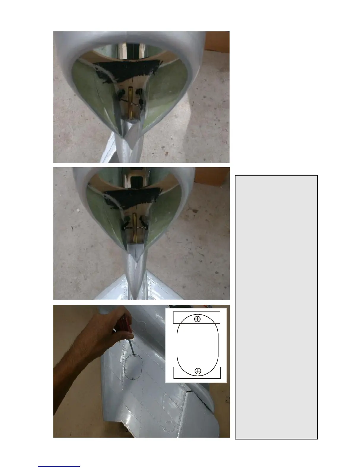
These photos show, where to
cut or drill the holes for the
linkage to pass the rudder
post. These holes should be
fairly large, so that the linkage
does not bend ot lock at any
position.
When all is done and adjusted,
drill the holes for the hinges
into the rudder post of the
fuselage and insert the rudder
by applying epoxy glue to the
hinges.
After the glue has cured, finally
install the linkage and confirn
the free movement to both
sides.
Tip for the Pro’s:
This type of linkage is basically
a pull pull set up. the only
differenceis that not flexible
wires, but 2mm pushrods are
used. So, it could also be a
push/push linkage, whichcan
build up a very strong tension
in the system, if not done right.
To set this type of linkage up
properly you have to adjust the
length of both pushrods
exactly, before you install the
servo horn to the servo. If all is
tension free, the servo horn will
slide on the servo axle easily,
after the whole linkageis set
up. Last thing is then to put in
and tighten the center screw.
You might usesome thread
locker to make sure that the
screw doesn’t comeloose.
Do not make a support at the
bottom end of the torsion
linkage, as theangles of the 2
pushrods are not exactly
parallel, and it would build up a
very dangerous tension at
maximum travel, if the rudder
torsion linkage didn’t have a
slight flexibility. Thereis no
one-way-load on the bottom
point of the torsion linkage, as
all force pulling on the one
side, the same force is pushing
in the opposite direction on
the other side.