7. Elevator and Top Rudder
Work Steps:
- install the hinges and torsion linkage in the elevator
- install the elevator servos and set up the linkage
- glue elevator in and glue in the fixed part of rudder
You need:
- 5 mm drill bit, dremel milling tool, philips screw driver
small pliers, small round file, sand paper
- epoxy glue, CA-Glue
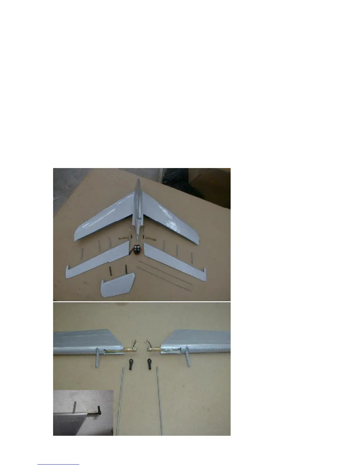
- one-piece-stab, both elevators, top rudder
- 2 torsion linkages, 6 hinges, 2 carbon dowels, M2 push rods,
2 clevises M2, 2 threaded ends M2, 2 elevator mini servos
The elevator servos are
hooked to a hidden torsion
linkage, which does not
interfere with any scale
ambitions in regards to static
judging. This torsion linkage is
glued into the elevator
controls.
Start with mounting this torsion
linkage and the Robart hinge
pins into the elevators. You did
the same thing with the rudder
already, so follow these steps
accordingly again.
Drill the holes in the spars of
the one-piece-stab and trial
mount the elevators to the
stab. Use the same directions
as given on the aileron mount,
resp. the angle of the hinges,
so that you can assemble the
elevators and the stab due to
the swept back shape. After
that cut the center hole as
shown in the drawing, to have
access to the servo area inside
the stab.
Move the elevatorscarfully,
and look inside to se whether
the balls of the torsion linkage
hit the fiberglass somewhere.
You might have to bend the
steel arm of the torsion linkage
slightly to manage a smooth
travel.
Inside the stab there is a
vertical spar. There are
premilled holes inside, which
size might have to be
enlarged, so that the linkage
can be put through.