Do you have a question about the CARLO GAVAZZI WM30-96 and is the answer not in the manual?
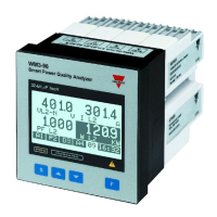
Details the components and functions of the instrument's display and keyboard.
Explains the secondary functions of instrument buttons via long press.
Explains the various elements and icons shown on the instrument's display screen.
Details how to set alarm thresholds for up and down alarms.
Covers initial setup like password, backlight time, and module recognition.
Explains settings for electrical system type, CT/PT ratios, DMD calculation, and SET POWER.
Details how to set the home page display and configure digital filters.
Provides options for selecting variables displayed on the home page based on system type.
Explains the concepts and operation of fixed and sliding selection for AVG/DMD calculation.
Guides configuration for RS485, Ethernet, and BACnet communication ports.
Details how to set up virtual alarms, link them to digital outputs, and configure pulse outputs.
Explains programming for analogue outputs, including MIN/MAX input/output values.
Covers resetting energy meters and configuring the instrument's clock.
Explains how FILTER S and FILTER CO parameters affect measurement stability and response.
Provides practical examples for programming digital filters to stabilize fluctuating values.
Details how to program the instrument to retransmit power values via a 0-20mA output.
Explains programming for retransmitting Power Factor (PF) values via a 0-20mA output.
Covers initial steps like removing covers, locking programming, and sealing modules.
Provides diagrams and descriptions for various electrical connections and wiring configurations.
Lists the specific electrical connections for different modules (e.g., MO 02, MO R2, MC 485 232).
Shows wiring diagrams for various system types (3-phase, 2-wire, etc.) and load conditions.
| Frequency Range | 45 to 65 Hz |
|---|---|
| Mounting | Panel mount |
| Type | Power Meter |
| Display | LCD |
| Input Current | 0 to 5 A AC (via CT) |
| Measurement Type | Voltage; Current; Power; Energy; Frequency |
| Accuracy | Class 0.5S (according to EN62053-22) |
| Communication | RS485 Modbus RTU |
| Power Supply | 100 to 240 VAC, 50/60 Hz or 100 to 300 VDC (depending on model) |
| Storage Temperature | -30 to +70 °C |
| Dimensions | 96x96x65mm |
| Protection Class | IP20 (terminals) |