Do you have a question about the Carman AUTO-i 700 and is the answer not in the manual?
General guidance for safe and efficient product use.
Lists and explains the various capabilities of the AUTO-i 700 scanner.
Details technical specifications like dimensions, CPU, memory, display, and operating conditions.
Explains features and handling precautions for the rechargeable battery pack.
Lists the parts included in the basic kit for the AUTO-i 700.
Details various cables and adapters for the Asian vehicle kit.
Lists cables and adapters for European and USA/Australian vehicle kits.
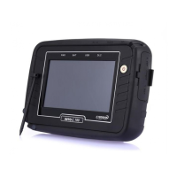
Illustrates and describes key product components and their functions.
Identifies and explains various connectors on the device.
Describes the carrying case for protection and storage.
Describes the rubber shroud protecting the device.
Explains the Wi-Fi USB dongle for wireless connectivity.
Details the DLC cable (OBD-II cable) for vehicle diagnosis.
Lists various DLC adapters for different vehicle manufacturers.
Explains different methods of powering the AUTO-i 700 device.
Provides initial steps and checks before using the system.
Describes the main screen menus like OBD2/EOBD, CAR, DOWNLOAD, CONFIG, UTILITY.
Explains the meaning of icons displayed on the main screen.
Explains icons used in the CAR menu, including Capture, Setting, Home, and Back.
Allows setting up language, sound, brightness, and connecting HDMI for the LCD display.
Details options for configuring graph display settings like colors, grids, and line width.
Enables selection of favorite vehicle makers to customize the diagnosis menu.
Allows adjusting the date and time settings stored in the device's internal memory.
Guides on how to connect to a Wi-Fi router using the device.
Explains how to set a password to restrict device usage to specified users.
Displays system, license, and user information, and allows editing of user details.
Allows saving and analyzing vehicle parameter data for intermittent symptom diagnosis.
Enables saving measured values and parameter data for specific times during diagnosis.
Explains how to capture and save screenshots, including the red marker function.
Guides on connecting the device and selecting a vehicle for diagnosis.
Allows selecting the vehicle manufacturer from a list for diagnosis.
Guides on selecting the specific vehicle system (e.g., Engine, ABS) for diagnosis.
Checks for malfunctions by displaying and explaining DTCs (Diagnostic Trouble Codes).
Explains how to clear Diagnostic Trouble Codes (DTCs) from the vehicle's ECU.
Allows checking sensor values and control data for selected vehicle systems.
Enables forced start/stop of actuators and switches for diagnosis.
Resets ECU adaptive values to clear learned data.
Checks for leaks in the fuel tank's evaporation system.
Prevents adjustment of data or programs from the ECU.
Checks the number of misfires in each cylinder and the reason.
Displays system model and software version information.
Explains the purpose and regulations of OBD-II/EOBD for emission diagnosis.
Guides on connecting to OBD-II/EOBD vehicles and selecting the diagnosis program.
Checks communication with ECU modules to review general response items.
Allows checking parameter data specified by the OBD-II/EOBD standard.
Checks the current vehicle's trouble codes.
Explains how to clear DTCs from the vehicle's system.
Displays monitoring test results while the vehicle is operated.
Allows control and testing of functions related to the OBD-II system.
Displays information about the ECU installed in the vehicle.
Guides on installing the vehicle diagnosis program using a USB cable.
Guides updating the device using a USB memory stick.
Explains how to update the device using a Wi-Fi dongle.
Explains how to register the product on the website.
Provides troubleshooting steps for communication failure issues.
Outlines the manufacturer's warranty terms and conditions for the product.
Details the warranty period and software update policy.
Provides instructions for requesting repair service for the product.
| Brand | Carman |
|---|---|
| Model | AUTO-i 700 |
| Category | Diagnostic Equipment |
| Language | English |