I N S T R U C T I O N S
For the installation and maintenance of DS1525 - DS1550 -
DS2525 - DS2550 desuperheaters
IMI0030E.doc
Rev.4 20/08/12
20090 SEGRATE (MI)- via E.Fermi
EMAIL: info@carrarovalvole.it
TEL.(02) 269912.1 - FAX.(02) 2692.2452
Page 8 of 17
8 INSTALLATION AND ASSEMBLY INSTRUCTIONS
DS1525 – DS1550 – DS2525 – DS2550
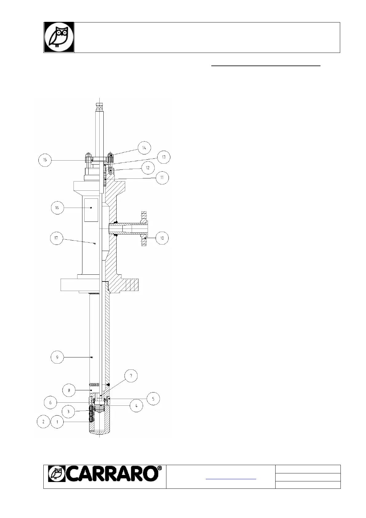
8.1 Cross-section drawings
• DS1525 – DS1550:
Pos. Part name Material
1+ 2 • Spray nozzle assembly AISI 410
3 • Piston ring AISI 431 Nitrided
4 • Piston AISI 420
5 • Tightening ring A-182 F11-F22
6 Seat Stellite 6
7 • Plunger AISI 431
8 Seat housing A-182 F11
9 Body pipe A-335 P11 / P22
10 Water flange
A217 WC6 o A182 F11/F22
11 • Gasket Graphite
12 Stud A-193 B7
13 • Packing gland AISI 431
14 Nut A-194 2H
15 Gland plate AISI 304
16 Name plate AISI 304
17 Central body A-217 WC6 / WC9
• RECOMMENDED SPARE PARTS
• DS2525 – DS2550:
Pos. Part name Material
1+ 2 • Spray nozzle assembly AISI 410
3 • Piston ring AISI 431 Nitrided
4 • Piston AISI 420
5 • Tightening ring A-182 F91
6 Seat Stellite 6
7 • Plunger AISI 431
8 Seat housing A-182 F91
9 Body pipe A-182 F91
10 Water flange A-182 F91
11 • Gasket Graphite
12 Stud A-193 B7
13 • Packing gland AISI 431
14 Nut A-194 2H
15 Gland plate AISI 304
16 Name plate AISI 304
17 Central body A-182 F91
• RECOMMENDED SPARE PARTS
Fig.1
 Loading...