EasyManua.ls Logo

Carrier 24APA - User Manual

Carrier 24APA
18 pages
To Next Page IconTo Next Page
Loading...
Installation Instructions
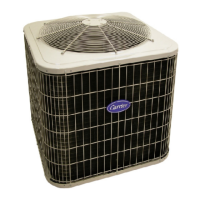
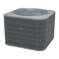
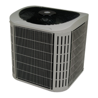
24APA
Performancet Series Air Conditioner
with Puronr Refrigerant
1---1/2 to 5 Nominal Tons (Size 18 To 60)
the environmentally sound refrigerant
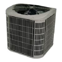
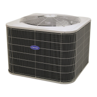
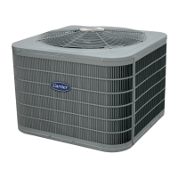
Fig. 1 --- 24APA
NOTE: Read the entire instruction manual before starting the
installation.
TABLE OF CONTENTS
PAGE
SAFETY CONSIDERATIONS 2......................
INSTALLATION RECOMMENDATIONS 2............
INSTALLATION 3--9,14............................
Step 1 -- Check Equipment & Jobsite 3................
Step 2 -- Install on Solid Pad 3......................
Step 3 -- Clearance Requirements 3...................
Step 4 -- Operating Ambient 3.......................
Step 5 -- Install TXV 3 -- 4.........................
Step 6 -- Make Piping Connections 5 -- 7..............
Step 7 -- Make Electrical Connections 7 -- 8............
Step 8 -- Compressor Crankcase Heater 8..............
Step 9 -- Install Electrical Accessories 8..............
Step 10-- Check OCT and OAT Thermistor Attachment 8..
Step 11 -- Start--Up 8 -- 9...........................
Step 12 -- Check Charge 9, 14.......................
GENERAL SEQUENCE OF OPERATION 9............
CONTROL FUNCTIONS
AND SEQUENCE OF OPERATION 10 -- 11.............
TROUBLESHOOTING 11 -- 12........................
FINAL CHECKS 13.................................
CARE AND MAINTENANCE 13......................
SUBCOOLING TABLE 14............................
24 VOLT CONNECTION DIAGRAMS 15 -- 16...........
PURONR REFRIGERANT QUICK REF. GUIDE 17.....

Questions and Answers:

Carrier 24APA Specifications

General IconGeneral
Model24APA
RefrigerantR-410A
Compressor TypeScroll
Voltage208/230V
Phase1
TypeAir Conditioner
Cooling Capacity24, 000 BTU
HSPF RatingNot Applicable
WeightVaries by unit size
Sound Pressure Level (Indoor)Varies by model
Sound Pressure Level (Outdoor)Varies by model
Indoor Unit Dimensions (H x W x D)Varies by model
Outdoor Unit Dimensions (H x W x D)Varies by model
Indoor Unit WeightVaries by model
Outdoor Unit WeightVaries by model

Summary

Safety Considerations

Installation Recommendations

Installation Best Practices

Provides 10 key recommendations for optimal installation and performance.

Installation Steps

Initial Installation Steps

Covers jobsite check, pad installation, clearance, and operating ambient requirements.

Install TXV

Detailed instructions for installing the Thermostatic Expansion Valve (TXV).

Make Piping Connections

Guidance on connecting refrigerant piping, including tube sizes and brazing.

Make Electrical Connections

Detailed steps for making safe and correct electrical wiring connections.

Install Accessories & Check Sensors

Install crankcase heater, accessories, and check thermistor attachments.

System Start-Up and Charge Check

Procedures for system start-up and verifying the refrigerant charge.

General Sequence of Operation

Control Functions and Sequence of Operation

Cooling Operation Description

Details on how the unit operates during cooling mode with different thermostats.

Communication & Status Lights

Explanation of the COMM and STATUS indicator lights on the control board.

Crankcase Heater Operation

Information on when the crankcase heater is energized and its purpose.

Outdoor Fan Motor Operation

How the outdoor fan motor operates during normal and fault conditions.

Time Delays Explained

Overview of the various time delays built into the unit's operation.

Utility Interface Function

How the unit interacts with external utility control signals for load management.

Low Ambient Cooling

Provisions and operation modes for cooling at low outdoor temperatures.

Troubleshooting

System Communication Failure

Diagnosing issues when communication between system components fails.

Pressure Switch Protection

How high and low-pressure switches protect the compressor and system.

Control Faults

Identifying and resolving faults related to the outdoor unit control board.

24 V Brown Out Protection

Understanding and addressing issues with low control voltage (brown outs).

Compressor Voltage Sensing

Monitoring compressor voltage to detect potential operational problems.

Compressor Thermal Protection

Troubleshooting compressor thermal cutout or loss of 230V power.

Contactor Issues

Diagnosing contactor shorts and related wiring errors.

No 230 V at Compressor

Troubleshooting lack of 230V power at the compressor terminals.

Temperature Thermistors

Understanding thermistor function and troubleshooting sensor failures.

Thermistor Sensor Comparison

Checking for proper sensor readings and identifying out-of-range conditions.

Failed Thermistor Default Operation

How the system operates when thermistors fail and default settings are used.

Status Codes

Interpreting amber LED flash codes for system diagnostics and fault identification.

Final Checks

Wiring and Tubing Security

Ensuring all wiring and tubing is properly routed and secured.

Service Valve Stem Tightness

Verifying the correct tightness of service valve stem caps.

Owners Manual and Checklist

Leaving documentation and explaining system operation to the owner.

Care and Maintenance

Subcooling Table

Required Liquid-Line Temperature Table

Table correlating liquid pressure and required subcooling temperature for charging.

24 Volt Connection Diagrams

Infinity Control Wiring Diagrams

Wiring diagrams for Infinity Control systems with 4-wire connections.

Standard Thermostat Wiring

Wiring diagrams for non-communicating thermostats with 3-wire connections.

Puron Refrigerant Quick Reference Guide

Related product manuals