Do you have a question about the Carrier INFINITY 24ANA and is the answer not in the manual?
Inspect unit and job site for damage and verify specifications match job requirements.
Mount the unit on a level pad, using tie-downs if required by codes or conditions.
Maintain specified clearances for airflow, wiring, piping, and service access.
Define minimum (55°F) and maximum (125°F) outdoor operating temperatures for cooling.
Install the Thermostatic Expansion Valve (TXV) for Puron systems, replacing fixed orifice devices.
Connect refrigerant tubing, emphasizing POE oil protection and system evacuation.
Connect field wiring to the unit, ensuring compliance with codes and proper grounding.
Instructions for powering the compressor crankcase heater before starting the unit.
Refer to individual instructions for installing accessory kits and components.
Procedures for selecting appropriate airflow settings for different furnace and fan coil combinations.
Steps to properly start up the system after installation, including evacuation and initial operation.
Overview of two-stage cooling operation, communication lights, and system modes.
Procedure for verifying and adjusting the system's refrigerant charge using subcooling.
Diagnosing and resolving communication issues between system components.
Importance of a valid model plug for unit operation.
Response to high or low pressure switch trips and lockout conditions.
Actions to take when the outdoor unit control board fails.
How the unit reacts to low voltage conditions and brown outs.
Verifying 230V power at the compressor contactor for cooling demand.
Monitoring compressor motor voltage status for potential issues.
Identifying if a contactor is stuck closed when no demand exists.
Control response to thermal protector trips in 24ANA7 models, including lockout.
Control response to thermal protector trips in 24ANA1 models, including lockout.
Diagnosing open contactors for low/high stages when compressor should be starting.
Monitoring start voltage at VR/VS terminals for 24ANA7 compressor starts.
Troubleshooting pressure/current changes during stage transitions for 24ANA7.
Troubleshooting pressure/current changes during stage transitions for 24ANA1.
Overview of key components like the 2-stage control board and compressor.
Explanation of thermistors sensing outdoor ambient and coil temperatures.
How the control compares outdoor and coil sensor readings for proper operation.
Default operations and limitations when outdoor air or coil thermistors fail.
Interpreting amber status light flashes to diagnose system problems and fault codes.
Indicates normal system operation when no call for unit activity is present.
Operating the 24ANA1 in emergency mode with a standard thermostat.
Diagnosing and resolving communication issues via status codes.
Troubleshooting status codes for missing or invalid model plugs.
Status codes and actions for high-pressure switch trips.
Status codes and actions for low-pressure switch trips.
Status codes for verifying 230V power at the contactor.
Status codes for troubleshooting outdoor air temperature sensor faults.
Status codes for troubleshooting outdoor coil temperature sensor faults.
Status codes for improper sensor relationships between coil and outdoor air.
Status codes for low stage thermal protector trips and control response.
Status codes for high stage thermal protector trips and control response.
Status codes for detecting a stuck closed contactor.
Status codes for troubleshooting no 230V supply to the compressor.
Status codes for investigating low stage start voltage failures.
Status codes for lockout after consecutive low stage start failures.
Status codes for investigating high stage start voltage failures.
Status codes for lockout after consecutive high stage start failures.
Status codes for thermal cutout in multiple low stage cycles leading to lockout.
Status codes for thermal cutout in multiple high stage cycles leading to lockout.
Status codes for lockout after consecutive low pressure switch trips.
Status codes for lockout after consecutive high pressure switch trips.
Status codes for diagnosing an open low stage contactor.
Status codes for diagnosing an open high stage contactor.
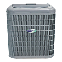
| Brand | Carrier |
|---|---|
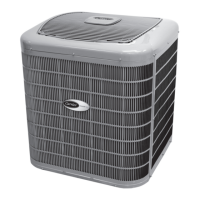
| Model | INFINITY 24ANA |
| Category | Air Conditioner |
| Language | English |


 Loading...