10
FOLLOW THESE STEPS TO PROPERLY START
UP
SYSTEM:
1. After system is evacuated, fully open liquid and vapor service
valves.
2. Unit is shipped with valve stem(s) closed and caps installed.
Replace stem caps after system is opened to refrigerant flow (back
seated). Replace caps finger--tight and tighten with wrench an
additional 1/12 turn.
3. Close electrical disconnects to energize system.
4. Set room thermostat at desired temperature. Be sure set point
is below indoor ambient temperature.
5. Set room thermostat to HEAT or COOL and fan control to ON
or AUTO mode, as desired. Operate unit for 15 minutes. Check
system refrigerant charge.
CAUTION
!
UNIT OPERATION AND SAFETY HAZARD
Failure to follow this caution may result in minor personal injury ,
equipment damage or improper operation.
To prevent compressor damage or personal injury,
observe the following:
S Do not overcharge system with refrigerant.
S Do not operate unit in a vacuum or at negative pressure.
S Do not disable low pressure switch in scroll compressor
applications.
S Dome temperatures may be hot.
S In 3 phase applications, incorrect phasing will cause reverse
rotation, resulting in elevated noise levels, equalized
pressures and reduced current draw. Correct by reversing
power connection L1 and L2 on contactor.
24 VAC HOT
R
C
W2
Y
G
R
C
RVS COOLING
C
W2
HP THERMOSTAT
TYPICAL
FAN COIL
HEAT
PUMP
G
O
E
W2
E
W3
R
Y
24 VAC COM
HEAT STAGE 2
COOL/HEAT
STAGE 1
INDOOR FAN
EMERGENCY
HEAT
O
*
*
*
IF AVAILABLE
*
LEGEND
24-V FACTORY WIRING
24-V FIELD WIRING
FIELD SPLICE CONNECTION
OUTDOOR THERMOSTAT
EMERGENCY HEAT RELAY
SUPPLEMENTAL HEAT RELAY
SHR
EHR
ODT
A02325 / A97413
Fig. 11 -- Generic Wiring Diagrams
(See Thermostat Installation Instructions for specific unit
combinations)
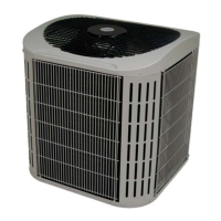
25HBA
 Loading...