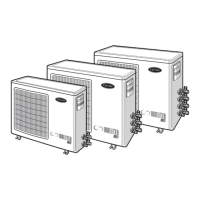
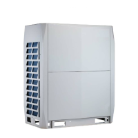
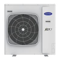
This document serves as the Installation and Owner's Manual for Carrier XCT7 side discharge outdoor units, specifically models 38VS125C7SHQEE and 38VS140C7SHQEE. It provides comprehensive guidelines for installation, operation, and maintenance, ensuring safe and efficient use of the air conditioning system.
The outdoor unit operates on a "simultaneous control" principle, meaning all connected indoor units will operate in either heating or cooling mode concurrently. To protect the compressor, it is recommended to power on the unit for at least 12 hours before initial startup. This manual focuses on the outdoor unit's installation, while indoor unit installation requires consulting their respective manuals.
Function Description:
The Carrier XCT7 outdoor unit is designed for multi-split air conditioning systems, providing either cooling or heating for connected indoor units. It incorporates advanced features to ensure optimal performance and safety. The unit is designed to operate within specified temperature ranges:
- Cooling (Dry): Indoor temperature range is 18°C DB (Dry Bulb) / 14°C WB (Wet Bulb) minimum to 32°C DB / 23°C WB maximum. Outdoor temperature range is -5°C DB minimum to 52°C DB / 26°C WB maximum.
- Heating: Indoor temperature range is 15°C DB minimum to 27°C DB maximum. Outdoor temperature range is -15°C DB minimum to 21°C DB / 15°C WB maximum.
The unit features a 5-minute delay function for compressor startup after power-off, preventing damage. In heating mode, the outdoor defrosting process may affect heating efficiency, causing condensate to flow and vapor to appear, which is normal. The indoor fan motor may reduce speed or stop, and the outdoor motor will stop during defrosting. The system includes a high-pressure switch as a protection device, which automatically stops the unit in abnormal operating conditions. In case of a power failure, the unit will halt operations and, if equipped with a restart function, will resume its previous state upon power restoration.
Important Technical Specifications:
The outdoor unit contains fluorinated greenhouse gases (R410A) covered by the Kyoto Protocol, with a GWP (Global Warming Potential) value of 2088. It is crucial not to vent this refrigerant into the atmosphere.
Refrigerant Piping:
- Pipe Diameter: The manual specifies pipe diameters for gas and liquid lines based on total indoor capacity. For X<112 (100W), gas pipe is Ø15.88mm and liquid pipe is Ø9.52mm. For 112≤X<234 (100W), gas pipe is Ø19.05mm and liquid pipe is Ø9.52mm.
- Copper Pipe Selection: The manual provides a table for copper pipe hardness and thickness, with minimum thicknesses ranging from 0.8mm to 1.4mm depending on the outer diameter. For coil pipes with an outer diameter of 19.05mm, the thickness must be over 1.1mm.
- Allowable Pipe Length and Height Difference: The total length of piping (actual length) is 120m, with a longest piping length of 60/70m. The piping length of the indoor unit furthest from the first branch piping is 40m. The maximum drop height between indoor and outdoor units is 30m (above outdoor) or 20m (under outdoor), and between indoor units is 10m.
- Additional Refrigerant Charging: The additional refrigerant amount is calculated based on the actual length of the liquid pipe and an additional amount per meter liquid pipe, with specific values provided for different pipe diameters (e.g., 0.35 kg/m for Ø22.22mm, 0.25 kg/m for Ø19.05mm, etc.).
Electrical Specifications:
- Power Supply: The models 38VS125C7SHQEE and 38VS140C7SHQEE operate on 1PH, 220-240V~, 50/60Hz.
- Circuit Breaker: For 38VS125C7SHQEE, a 32A circuit breaker is required, with a 30mA ground fault interrupter (response time below 0.1s). For 38VS140C7SHQEE, a 40A circuit breaker is required, with a 30mA ground fault interrupter (response time below 0.1s).
- Power Cable Section: 6mm² for 38VS125C7SHQEE and 10mm² for 38VS140C7SHQEE.
- Ground Wire Section: 6mm² for 38VS125C7SHQEE and 10mm² for 38VS140C7SHQEE (M5 screw).
- Communication Wire: A 0.75mm² x 3-core shielding line is used for wired controllers, with a total length not exceeding 250m. The shielding layer must be grounded at one end.
Sound Power Level (dBA):
- 38VS125C7SHQEE: 69 dBA (Cooling), 71 dBA (Heating).
- 38VS140C7SHQEE: 71 dBA (Cooling), 73 dBA (Heating).
Shipping Weight: Both models have a shipping weight of 97 kg.
Usage Features:
- Installation Location: The unit should be installed in a sturdy, well-ventilated place, away from flammable gases, corrosive gases, salty air, coal smoke, high humidity, Hertzian wave-emitting devices, and areas with significant voltage changes. It should also be positioned to minimize noise disturbance to neighbors.
- Manual Handling: Two or more people are required to carry the outdoor unit, ensuring it remains level and using external protection like cloth or cardboard. The wood base should not be demolished.
- Refrigerant Pipe Connection: Pipes can be connected from four directions (front/rear hole, cover hole, or directly across the floor). Special tools for R410A are required for flaring and connecting pipes, and double spanners should be used for tightening.
- Leakage Test: After piping installation, a leakage test must be performed using nitrogen, applying pressure step-by-step to reach 4.0MPa and maintaining it for over 1 day.
- Evacuation: The system must be evacuated at the liquid stop valve and both sides of the gas stop valve.
- Check Valve Operation: The liquid and gas stop valves should be fully opened using a hexangular spanner, and the valve caps tightened to the specified torque.
Maintenance Features:
- Regular Inspection: Before wiring or regular inspection, the main power switch of both indoor and outdoor units must be turned off for at least 1 minute.
- Wiring Protection: Wires and electrical components should be protected from rats or other animals, and contact with refrigerant pipes, steel edges, and electrical components should be avoided to prevent damage and fire hazards.
- Grounding: The unit must be properly grounded according to EN 60364.
- Insulation Resistance: Before startup, the insulation resistance between the ground and electrical device terminals should be measured and must be greater than 1 MΩ.
- Pipe Insulation: Adequate heat insulation measures must be taken for liquid and gas pipes to prevent condensation and wetness.
- Drainage: The drainage pipe should be installed to ensure fluent drainage and heat insulation against condensation.
- Refrigerant Recycling: Before scrapping, moving, setting, or repairing the air conditioning unit, the refrigerant must be recycled by qualified enterprises.
- Troubleshooting: The manual provides a comprehensive list of failure codes displayed on the master unit's digital tube, along with their definitions and remarks, to assist in diagnosing and resolving issues. These codes cover various malfunctions, including sensor failures, communication errors, pressure switch faults, and IPM module protection.