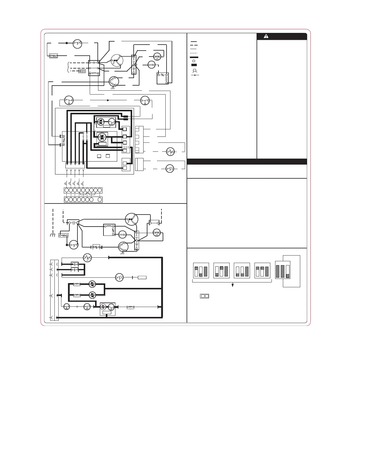
Fig. 1—Label Wiring 327207-101
A05014
SPEED
UP
THIS DEFROST CONTROL BOARD CONTAINS A FIVE MINUTE SHORT CYCLE
PROTECTOR. A FIVE MINUTE DELAY WILL OCCUR BETWEEN COMPRESSOR
OFF/ON CYCLES.
* MAY BE FACTORY OR FIELD INSTALLED
COMP COMPRESSOR
CTD COMPRESSOR TIME DELAY
CONT CONTACTOR
CB CIRCUIT BOARD
DFT DEFROST THERMOSTAT
DR DEFROST RELAY AND CIRCUITRY
*HPS HIGH PRESSURE SWITCH
*LPS LOW PRESSURE SWITCH
OFM OUTDOOR FAN MOTOR
RVS REVERSING VALVE SOLENOID
RVSR REVERSING VALVE SOLENOID RELAY
*SC START CAPACITOR
*SR START RELAY
*ST START THERMISTOR
FIELD SELECTABLE OPTIONS FOR TIME PERIOD BETWEEN DEFROST
CYCLES (MINUTES)
- LEGEND -
123
123
123
123
30 MINUTES 60 MINUTES
(DEFAULT)
90 MINUTES
120 MINUTES
120
30
OR
OR
OR
60
90
DIP SWITCH SETTINGS
123
QUIET
SHIFT
ON
OFF
(DEFAULT
NOTE
1) MOMENTARILY SHORT PINS AND RELEASE TO BYPASS COMPRESSOR OFF DELAY.
2) SHORT FOR 5+ SEC. AND RELEASE FOR FORCED DEFROST.
3) PERMANENT SHORT WILL BE IGNORED. DEFROST WILL TERMINATE IN 30 SEC. IF
DFT OPEN. DEFROST WILL TERMINATE NORMALLY IF DFT IS XLOSED.
FACTORY POWER WIRING
FIELD POWER WIRING
FACTORY CONTROL WIRING
FIELD CONTROL WIRING
CONDUCTOR ON CIRCUIT BOARD
COMPONENT CONNECTION
1/4-INCH QUICK CONNECT TERMINALS
FIELD SPLICE
JUNCTION
AUXR AUXILLARY HEAT RELAY
CAP CAPACITOR (RUN)
*CH CRANKCASE HEATER
*CHS CRANKCASE HEATER SWITCH
- NOTES -
1. Compressor damage may occur
if system is over charged.
2. This unit is factory charged with
R-22 in accordance with the
amount shown on the rating plate.
The charge is adequate for most
systems using matched coils and
tubing not over 15 feet long. The
best performance will be
achieved when the
unit operates with a suction gas
superheat at the compressor inlet
of 5ºF at normal rating
conditions of the air conditioning
and refrigeration institute (ARI).
This chart may be used to
approximate the charge if ARI
rating conditions cannot be
obtained. ARI rating conditions
are equivalent to DOE test "A"
conditions. See product data
literature for required indoor air
flow rates and for use of line
lengths over 15 ft.
3. Relieve pressure and recover all
refrigerant before system repair or
final unit disposal. Use all service
ports and open all flow-control
devices, including solenoid valves.
CAU
TIO
N
JUMPERED TEST PINS (USE METAL OBJECT), FIELD SPEED-UP CYCLE
327207-101 REV. A
CONNECTION DIAGRAM
SCHEMATIC DIAGRAM
(LADDER FORM)
1. Compressor and fan motor furnished with inherent thermal protection.
2. To be wired in accordance with National Electric Code (N.E.C.) and local codes.
3. N.E.C. class 2, 24 V circuit, min. 40 VA required.
4. Use copper conductors only, from disconect to unit.
5. Must use thermostat and sub-base as stated in pre-sale literature.
6. If indoor section has a transformer with a grounded secondary, connect the
grounded side to "C" on the circuit board.
7. If any of the original wire, as supplied, must be replaced, use the same or
equivalent wire.
8. Check all electrical connections inside control box for tightness.
9. Do not attempt to operate unit until service valves have been opened.
10. When LPS and HPS are not required, a jumper will be installed between
Y and T1 on the defrost board.
11. Use conductors suitable for at least 75ºC (167ºF).
+t°
BLU
*ST
YEL
BLK
*CHS
YEL
YEL
5
2
1
YEL
GLER
W2
OYC
TERMINAL BLOCK
INDOOR UNIT
RED
WHT
ORN
YEL
BLK
CB
G
W3
LER
W2
OYC
BLU
BRN
YEL
*HPS
*LPS
2323
21
11
BLU
S
C
R
YEL
BRN
L2
L1
BLK
CONT
EQUIP
GND
INDOOR THERMOSTAT (NOTE #5)
SUPPLY
POWER
208/230 1Ø
BLK
BRN
OFM
*SC
*SR
BLU
YEL
CAP
BLK
COMP
YEL
BLK
BLK
*CH
BLK
BLU
DR
OF1
OF2
CY OW2R
LOGIC
Y
T1
LOGIC
T2
60
90
120
30
SPEED
UP
R
C
C
DFT
O
BRN
YEL
CESO130076-01
CTD
ORG
ORG
or
RVS
BLK
BLK
DFT
BLK
or
PNK
PNK
BLK
ORG
ORG
or
PNK
or
PNK
+t°
*ST
*CHS
*CH
23
R
C
S
5
2
1
LOGIC
LOGIC
C
CONT
T2
CTD
T1
C
*HPS
*LPS
Y
Y
DFT
DFT
C
RVS
R
R
W2
O
O
OF1 OF2
DR
L2
23
CONT
OFM
CAP
F
C
COMP
H
*SC
*SR
21
11
L1
CONT
RVSR
AUXR
RVSR
AUXR
GND
EQUIP
2
 Loading...