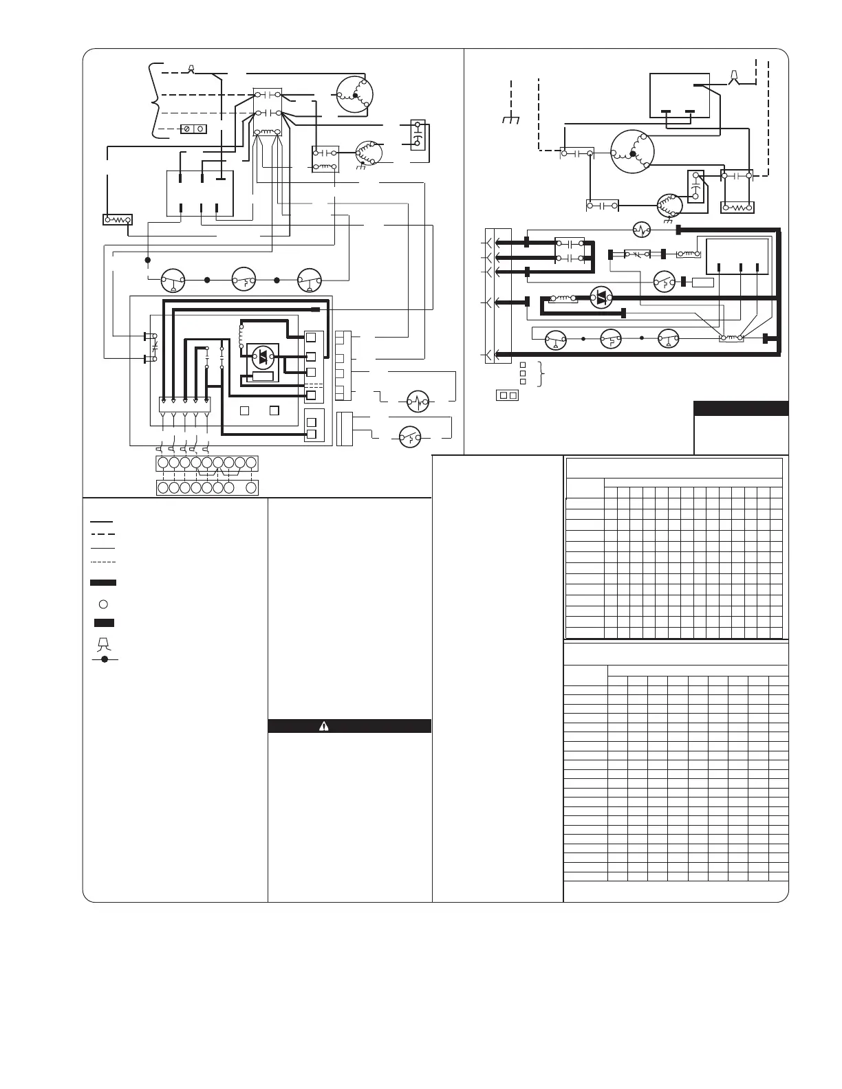
Fig. 8—Label Wiring 327416-101
A05021
FACTORY POWER WIRING
FIELD POWER WIRING
FACTORY CONTROL WIRING
FIELD CONTROL WIRING
CONDUCTOR ON CIRCUIT
BOARD
COMPONENT CONNECTION
1/4 - INCH QUICK CONNECT
TERMINALS
FIELD SPLICE
JUNCTION
CAPACITOR (DUAL RUN)
CRANKCASE HEATER
COMPRESSOR
CONTACTOR
CIRCUIT BOARD
DEFROST THERMOSTAT
DEFROST RELAY AND
CIRCUITRY
DISCHARGE TEMP. SWITCH
HIGH PRESSURE SWITCH
LOW PRESSURE SWITCH
OUTDOOR FAN MOTOR
OUTDOOR FAN RELAY
PHASE ROTATION MONITOR
REVERSING VALVE
SOLENOID
CAP
*CH
COMP
CONT
CB
DFT
DR
*DTS
*HPS
*LPS
OFM
OFR
PRM
RVS
* MAY BE FACTORY OR FIELD INSTALLED.
-LEGEND-
327416-101 REV. B
SCHEMATIC DIAGRAM (LADDER FORM)
CONNECTION DIAGRAM
CONT
L1
11
21
EQUIP
GND
OFM
CONT
23
13
L3
T2
T1
T3
COMP
CAP
L2
L3 L1
L2
PRM
OFR
31
*CH
C
RVS
OO
W2
RR
YY
C
DFT
DFT
DR
*LPS
*DTS
*HPS
T1
C
CONT
LOGIC
CONT
COM
PRM
24V
OF1 DR OF2
OFR
PRM LED INDICATOR
NOTE
OFF: NO 24VAC
ON: OK
FLASH: PHASE PROBLEM
OFM
BLK
31
YEL
L2
23
13
21
11
L3
L1
EQUIP GND
CONT
*CH
OFR
CAP
BLK
*DTS
BLK
BLU
BRN
RED
WHT
ORN
YEL
BLK
CB
YEL
*HPS
*LPS
RW2OYC
OF2
OF1
LOGIC
DR
INDOOR UNIT
TERMINAL BLOCK
INDOOR THERMOSTAT
(NOTE #5)
CYO
W2
REL
W3
G
CYO
W2
REL G
YEL
BLK
BLU
BLK
(NOTE #11)
ALERT!
BLK
YEL
BRN
BRN
SUPPLY
POWER
460 3Ø
BLK or RED
BLK or RED
YEL
BLK
GRY
L3
L1
L2
CONT 24V COM
PRM
T2
T1
T3
COMP
YEL
BRN
BLU
BLK
YEL
BRN
BLU/YEL
BLU or YEL
BLK
YEL
ORG
ORG
or
or
RVS
BLK
BLK
DFT
BLK
or
PNK
PNK
or
BLK
PNK
PNK
ORG
ORG
R
R
DFT
90
30
SPEED
UP
Y
T1
C
C
O
HK32EA001
1. Compressor damage may occur if system is over
charged.
2. This unit is factory charged with R-22 in accordance
with the amount shown on the rating plate. The
charge is adequate for most systems using
matched coils and tubing not over 15 feet long.
The best performance will be achieved when the
unit operates with a suction gas superheat at the
compressor inlet of 5 ºF at normal rating conditions
of the air conditioning and refrigeration, institute
(ARI). This chart may be used to approximate the
charge if ARI rating conditions cannot be obtained.
ARI rating conditions are equivalent to DOE test "A"
conditions. See product data literature for required
indoor air flow rates and for use of line lengths over
15 Ft.
3. Relieve pressure and recover all refrigerant before
system repair or final unit disposal. Use all service
ports and open all flow-control devices, including
solenoid valves.
1. Compressor and fan motor furnished with
inherent thermal protection.
2. To be wired in accordance with National
Electric Code (N.E.C.) and local codes.
3. N.E.C. class 2, 24V circuit, min. 40 VA required.
4. Use copper conductors only, from disconnect
to unit.
5. Must use thermostat and sub-base as stated
in pre-sale literature.
6. If indoor section has a transformer with a
grounded secondary, connect the grounded
side to "C" on the circuit board.
7. If any of the original wire, as supplied, must
be replaced, use the same or equivalent wire.
8. Check all electrical connections inside control
box for tightness.
9. Do not attempt to operate unit until service
valves have been opened.
10. It is imperative to connect 3Ø field power
to unit with correct phasing. The Phase
Rotation Monitor will not allow the contactor
to be energized if thephasing is not correct.
If phasing is reversed, simply interchange any two
of the three power connections on the field side.
11. Use conductors suitable for at least 75ºC (167ºF).
NOTES:
CAU
TIO
N
COOLING ONLY
PROCEDURE
EVAPORATOR ENTERING AIR ºF WB.
TEMP °F
OUTDOOR
50
TABLE I - SUPERHEAT CHARGING TABLE
(SUPERHEAT ºF AT LOW-SIDE SERVICE PORT)
52 54 56 58 60 62 64 66 68 70 72 74 76
55 9 37
60 7
65 -- 6
70 -- -- 7
75 -- -- -- 6 9 12 15 18 21 24 28 31 34 37
80 -- -- -- -- 5 8 12 15 18 21 25 28 31 35
85 -- -- -- -- -- -- 8 11 15 19 22 26
90 -- -- -- -- -- --
--------------
-- -- -- -- -- -- --
--
--
--
--
--
----
--
----
--
----
--
------
--
-- --
--
5 9 13 16 20 24 27 31
95 6
100 8 12 15 20 23 27
5 9 13 17 22 26
6
8
--
--
-- --
-- -- --
105
110
115
918987858381797775
40
898785838179777573
38
878583817977757371
36
858381797775737169
34
838179777573716967
32
817977757371696765
30
797775737169676563
28
777573716967656361
26
757371696765636159
24
737169676563615957
22
71
6967656361595755
20
696765636159575553
18
676563615957555351
16
656361595755535149
14
636159575553514947
12
615957555351494745
10
595755535149474543
8
575553514947454341
6
555351494745434139
4
535149474543413937
2
5149
47454341393735
0
85.782.479.276.073.070.067.164.2
SUCTION PRESSUR E AT SERVI CE PORT PSIG.
TEMP. °F
61.5
SUPERHEAT
45
43
41
39
42
40
35
32
29
4038
35
3330
38
3633
3633
30
27
30
2724
33
18
29
30
22 25
14
10
23
2520
18
14
1511
2723
23
18
1512
10
26
23
20
17
14
12
24
21
19
16
13
10
21
19
16
13
10
TABLE II - REQUIRED SUCTION TUBE TEMPERATURE ºF
(MEASURED AT LOW-SIDE SERVICE PORT)
1. Operate unit a minimum of
10 minutes before checking
charge.
2. Measure suction pressure
by attaching a gage to
suction valve service port.
3. Measure suction temperature
by attaching an accurate
thermistor type or electronic
thermometer to the suction
line at service valve.
4. Measure outdoor air dry-bulb
temperature with a
thermometer.
5. Measure indoor air (entering
indoor coil) wet bulb
temperature with a sling
psychrometer.
6. Refer to table I. Find out-
door temperature and
evaporator entering air wet-
bulb temperature at this
intersection note the super-
heat.
7. Refer to table II. Find super-
heat temperature located in
step 6 and suction pressure,
at this intersection note
suction line temperature.
8. If unit has a higher suction
line temperature than charted
temperature, add refrigerant
until charted temperature
is reached.
9. If unit has a lower suction
line temperature than charted
temperature, remove and
recover refrigerant until
charted temperature is
reached.
10. If outdoor air temperature
or pressure at suction valve
changes, charge to new
suction line temperature
indicated on chart.
11. This procedure is valid when
indoor air flow is within
+/- 21% of its rated cfm.
FIELD SELECTED TIME PERIOD
BETWEEN DEFROST CYCLES (MINUTES)
JUMPERED TEST PINS (USE METAL OBJECT), FIELD SPEED-UP CYCLE
HEAT CYCLE:
90 MIN. ACCELERATED TO 21 SEC.
60 MIN. ACCELERATED TO 14 SEC.
50 MIN. ACCELERATED TO 12 SEC.
30 MIN. ACCELERATED TO 7 SEC.
10 MIN. ACCELERATED TO 2 SEC.
DEFROST CYCLE:
90
30
SPEED
UP
50
**
**
**
**
BOARD MAY HAVE 60
AS MIDDLE SELECTION
50
9
 Loading...