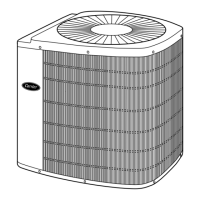
Electrical Data
UNIT
SIZE-SERIES
V/PH
OPER VOLTS* COMPRESSOR
FAN
FLA
MCA
60°C
MIN
WIRE
SIZE†
75°C
MIN
WIRE
SIZE†
60°C
MAX
LENGTH
(FT)‡
75°C
MAX
LENGTH
(FT)‡
MAX FUSE**
OR
CKT BKR
AMPS
Max Min LRA RLA
024-30
208/230/1 253 187
61.0 15.1 0.8 19.7 14 14 39 37 30
030-30 72.5 14.7 1.1 19.5 14 14 39 37 30
036-30 83.0 15.4 1.1 20.4 12 12 60 57 30
042-30 104.0 21.1 1.1 27.5 10 10 71 68 40
048-30 109.0 20.5 1.4 27.0 10 10 74 70 40
060-31 158.0 27.6 1.4 35.9 8 8 86 82 60
* Permissible limits of the voltage range at which unit will operate satisfactorily. Operation outside these limits may result in unit failure.
† If other than uncoated (non-plated), 60° or 75°C (140° or 167°F) insulation, copper wire (solid wire for 10 AWG and smaller, stranded wire for larger than 10 AWG)
is used, consult applicable tables of the NEC (ANSI/NFPA 70).
If wire is applied at ambient greater than 30°C (86°F), consult Table 310-16 of the NEC (ANSI/NFPA 70). The ampacity of nonmetallic-sheathed cable (NM), trade name
ROMEX, shall be that of 60°C (140°F) conductors, per the NEC (ANSI/NFPA 70) Article 336-30.
‡ Length shown is as measured 1 way along the wire path between the unit and the service panel for a voltage drop not to exceed 2 percent.
** Time-delay fuse.
FLA—Full Load Amps
LRA—Locked Rotor Amps
MCA—Minimum Circuit Amp
RLA—Rated Load Amps
NOTE: 1. Control circuit is 24v on all units and requires external power source.
2. Copper wire must be used from service disconnect to unit.
3. All motors/compressors contain internal overload protection.
Tested Combination Ratings*
UNIT SIZE-
SERIES
INDOOR
UNIT
ARI STANDARD RATINGS†
Cooling Heating
TC
SEER
EER
High-Temp Low-Temp
HSPF
Factory-
Supplied
Enhance-
ment
Standard
Rating
Carrier
Gas
Furnace
or
Accessory
TDR‡
Accessory
TXV**
TC COP TC COP
024-30 FX4ANF030 25,000 TDR & TXV 13.00 — — 11.50 25,000 3.30 16,600 2.30 8.00
030-30 FX4ANF030 29,000 TDR & TXV 13.00 — — 11.40 30,000 3.50 18,500 2.34 8.00
036-30 FX4ANF042 35,000 TDR & TXV 13.00 — — 11.30 35,000 3.35 21,600 2.34 7.70
042-30 FV4ANF003 40,500 TDR & TXV 13.10 — — 11.30 40,500 3.35 25,400 2.45 7.70
048-30 FV4ANF005 45,500 TDR & TXV 13.50 — — 12.00 47,500 3.50 28,300 2.50 8.50
060-31 FV4ANB006 58,500 TDR & TXV 13.20 — — 11.00 60,000 3.50 37,000 2.53 8.00
* Outdoor section/indoor section combination tested in accordance with DOE test procedure for heat pumps.
† Ratings are net values reflecting the effects of circulating fan heat. Supplemental electric heat is not included. Ratings are based on:
Cooling Standard: 80°F (27°C) db 67°F (19°C) wb indoor entering air temperature and 95°F (35°C) db air entering outdoor unit.
High-Temp Heating Standard: 70°F (21°C) db indoor entering air temperature and 47°F (8°C) db 43°F (6°C) wb air entering outdoor unit.
Low-Temp Heating Standard: 70°F (21°C) db indoor entering air temperature and 17°F (-9°C) db 15°F (-10°C) wb air entering outdoor unit.
‡ In most cases, only 1 method should be used to achieve TDR function. Using more than 1 method in a system may cause degradation in performance. Use either
the accessory Time-Delay Relay KAATD0101TDR or a furnace equipped with TDR. All Carrier furnaces are equipped with TDR except for the 58GFA.
** Based on computer simulation. TXV must be R-410A compatible and hard shutoff type.
COP—Coefficient of Performance
EER—Energy Efficiency Ratio
HSPF—Heating Seasonal Performance Factor
SEER—Seasonal Energy Efficiency Ratio
TC—Total Capacity (Btuh)
TDR—Time-Delay Relay
TXV—Thermostatic Expansion Valve
Sound Rating (dBA)
UNIT SIZE-SERIES SOUND RATING
024-30 70
030-30 72
036-30 74
042-30 73
048-30 76
060-31 76
4
 Loading...


