EasyManua.ls Logo

Carrier 40KMC012-7N User Manual

Carrier 40KMC012-7N
99 pages
To Next Page IconTo Next Page
Page #1 background imageLoading...
Page #1 background image
AM
PM
4 0 K M C - - - N
Installation manual
Manuale di installazione
Manuel d’installation
Installationsanweisung
Manual de instalación
Montage - Instructies
O K
Manual de instalação
InstallationSManual
Asennusohje

Table of Contents

Question and Answer IconNeed help?

Do you have a question about the Carrier 40KMC012-7N and is the answer not in the manual?

Carrier 40KMC012-7N Specifications

General IconGeneral
Energy Efficiency Ratio (EER)11.0
Compressor TypeRotary
Width (in)31.5
Cooling Capacity12000 BTU
RefrigerantR-410A
Voltage208/230V, 1-phase, 60Hz
Power Supply208/230V, 1-phase, 60Hz

Summary

Table IV: Material supplied

Installation instructions

Manual detailing the steps for installing the unit.

TABLE V Operating limits

Table VI: Components required for a complete installation

Electrical connecting cable between indoor and outdoor unit

Cable connecting the indoor and outdoor units electrically.

Table X: Fault code

Code

List of fault codes indicating system errors.

Description

Explains the cause and meaning of each fault code.

System configuration

Cooling only configuration (of the system)

Procedure to configure the unit for cooling-only operation.

Heat pump configuration (of the system)

Procedure to configure the unit for heat pump operation.

General information

Unit installation

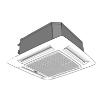
Instructions and guidelines for installing the indoor unit.

Choosing the installation site

Warnings: avoid...

Installation

Installation Procedures

Detailed steps for physically installing the unit.

Refrigerant connections

Pipe connection to the unit

Procedure for connecting refrigerant pipes to the unit.

Flaring the end of pipes

Method for preparing pipe ends for flare connections.

Electrical connections

SYSTEM CONFIGURATION

Multisplit/T-Kit configuration

Configuring the system for multisplit or T-Kit installations.

Cooling only configuration (of the remote controller)

Setting up the remote controller for cooling-only mode.

Operating test, address switch

Operating test (See tab.IX)

Procedure to test the unit's operation after installation.

Fault code and button T: “EMERGENCY"

Fault code (See fig. 51)

Explanation of fault codes indicated by unit LED flashes.

Button T: “EMERGENCY” (See fig. 51)

Functionality of the emergency button for manual operation.

Guide for the owner

Address selector

Related product manuals