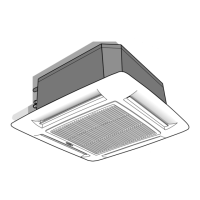
Do you have a question about the Carrier 40KQV050-7 and is the answer not in the manual?
Power input (watt) for cooling and heating.
List of components included with the unit for installation and use.
Main power supply voltage and operating limits.
List and specifications of parts needed for installation.
Guidelines and precautions for installing the indoor unit.
Recommendations and positions to avoid for unit placement.
Optional accessories available for the unit.
Prohibits specific installation methods, environmental conditions, and operational practices.
Guidance on unit positioning and air direction control for optimal room air distribution.
Preliminary steps before mounting the unit, including packaging and site preparation.
Instructions for physically attaching the unit using hangers and ensuring it is level.
Steps for making wall holes, installing pipes, and attaching the grille assembly.
Procedures for connecting refrigerant pipes to the unit, including torque specifications.
Detailed steps for preparing pipe ends for flare connections.
Identification of components and connections on the indoor unit control panel.
Guidelines for making electrical connections between units and mains supply.
Explains terminal box symbols and routing for connecting cables.
Details on installing grilles and ducts for fresh air intake and room air supply.
Instructions for directing conditioned air to an adjacent room.
Step-by-step guide to conduct operational tests after installation.
Criteria to verify during cool and heat mode tests.
Procedure for assigning unique addresses to indoor units for independent operation.
Explanation of fault code indicators (LEDs) and their meaning.
List of fault codes and their corresponding system error descriptions.
Description of the LEDs on the unit and their operational meanings.
Functionality of the emergency push-button for basic unit operation.
Advice for explaining unit operation and maintenance to the end-user.
| Brand | Carrier |
|---|---|
| Model | 40KQV050-7 |
| Category | Air Conditioner |
| Language | English |


