Do you have a question about the Carrier 42GW and is the answer not in the manual?
Common mistakes and situations to avoid during installation.
Proper installation and drainage requirements for the condensate pipe.
Details on connecting water pipes to the unit, including valve types.
Steps for assembling and mounting motorized thermo-electric valves.
Explains thermo-electric valve operation and field-supplied valve instructions.
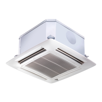
This document is an installation manual for the Carrier 42GW "Hydronic Global Cassette" Fan Coil Units. It provides comprehensive instructions for the installation, operation, and maintenance of these units, which are designed for air conditioning in various indoor environments.
The primary function of the Carrier 42GW units is to provide conditioned air (cooling or heating) to an indoor space. These fan coil units are designed for ceiling installation, specifically within a false ceiling, making them discreet and suitable for a wide range of commercial and residential applications. They operate by circulating water through a coil, which then exchanges heat with the room air, either cooling or heating it as required. Some models are also equipped with an electric heater for additional heating capacity.
The units offer flexible air distribution, with louvres that can be manually adjusted to control the direction of airflow. In cooling mode, the louvres can be positioned to direct air along the ceiling (Coanda effect) for optimal distribution, while in heating mode, they can direct air towards the floor to prevent hot air stratification. The control circuit ensures that the fan motor operates in conjunction with the motorized valve, preventing the valve from opening if the fan is not running. This intelligent control also manages the condensate discharge pump, ensuring continuous operation when the cold water regulating valve is open to prevent overflow.
The manual details the installation of motorized thermo-electric valves, which are crucial for controlling the water flow to the coil. These ON-OFF type valves have a slow stroke and are driven by the unit's ambient thermostat. They are normally closed towards the coil and open towards the bypass. When heating is required, an electric heater activates a thermostatic element, causing the valve to open after approximately 3 minutes, allowing water to circulate in the coil. Conversely, if the room temperature is satisfied or the unit is switched off, the valve closes towards the coil and opens towards the bypass after about 3 minutes. In case of an emergency, the valve can be manually opened by removing the electric head. The manual also provides instructions for installing field-supplied valves, emphasizing the use of valves that close the unit water inlet when there is no power supply.
The units are designed with provisions for fresh air intake and conditioned air supply to adjacent rooms. Side knockouts allow for the connection of ducts for these purposes. For fresh air intake, a supplementary fan (field-supplied) can be connected, operating in parallel with the thermo-electric control valve. An anti-freeze thermostat is recommended for winter operation with fresh air intake, with its bulb placed on the water outlet pipe before the supplementary fan. The fresh air flow should be less than 10% of the total air flow to avoid operational problems or excessive noise. For higher fresh air flow, a "primary air kit" is available, which uses a prepunched hole for air ducting and a baffle to introduce fresh air through a diffuser. For conditioned air supply to an adjacent room, the corresponding outlet must be closed using an air supply outlet obstruction kit. An air inlet grille should be fitted between the conditioned room and the adjacent room, or the door should be undercut.
The manual outlines several maintenance procedures to ensure the longevity and efficient operation of the unit. All cleaning and maintenance operations must be carried out by specially trained personnel, and the main power switch must be turned off before any service.
Filter cleaning is a key maintenance task. The acrylic air filter is washable in water and should be cleaned approximately every 6 months, depending on operating conditions. Electrostatic and active carbon filters, if used, are not washable and must be replaced. The filter can be easily accessed by opening the unit grille (turning two screws 90 degrees) and then extracting it. After vacuuming, the filter should be washed under tap water, dried, and replaced in its correct position.
Additional maintenance includes accessing the electric panel by removing its cover. This allows for inspection or replacement of internal components such as the fan motor, coil, condensate discharge pump, float switch, and electric heater (if fitted). These operations involve the removal of the condensate drain pan. The manual provides detailed instructions for condensate drain pan removal, including protecting the floor with a plastic sheet, removing the frame-grille assembly, draining condensate water into a bucket, and disconnecting electrical connections. The four fixing screws on the side of the drain pan must be removed to carefully take out the pan.
For prolonged shutdowns, the manual recommends cleaning or replacing unit air filters, checking and cleaning the drain pan and condensate discharge, and checking the tightness of electric connections before restarting the air conditioner. The manufacturer emphasizes that failure to observe installation instructions or use the unit outside specified operating limits will invalidate the unit warranty. It also warns against modifications or errors in electrical or water connections, which can lead to damage or fire hazards. The importance of proper grounding and insulation of pipes and valve assemblies to prevent condensation is also highlighted.
| Refrigerant | R410A |
|---|---|
| Voltage | 220-240V |
| Type | Wall Mounted Split System |
| Cooling Capacity | 12000 BTU |
| Power Supply | 220-240V, 50Hz |
| Weight | 32 kg (Outdoor) |
| Dimensions (H x W x D) | 550 x 780 x 290 mm (Outdoor) |