Do you have a question about the Carrier 48VL-A and is the answer not in the manual?
| Refrigerant | R-410A |
|---|---|
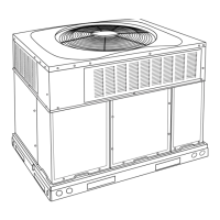
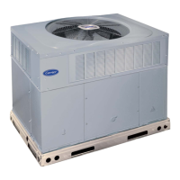
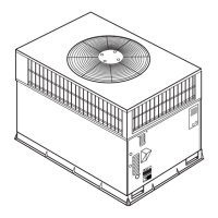
| Type | Air Conditioner |
| Compressor Type | Scroll Compressor |
| Indoor Unit Dimensions (L x W x H) | Varies by model |
| Outdoor Unit Dimensions (L x W x H) | Varies by model |
| Weight (Indoor Unit) | Varies by model |
| Weight (Outdoor Unit) | Varies by model |
| Power Supply | 208/230V, 1-phase, 60Hz |
| HSPF Rating | Not Applicable |
Verify unit model, serial number, and shipping papers.
Locate and check the unit's information plate for model and serial numbers.
Check for shipping damage before removing packaging materials.
Install unit support, considering hurricane tie-downs and roof curbs.
Install accessory roof curb, ensuring it is level for proper drain function.
Place unit on a solid, level pad at least 2 inches above grade.
Secure all ductwork to the unit flanges and building structure.
Ensure adequate clearances for combustion, ventilation, and condenser air.
Handle and install equipment using trained personnel and proper lifting techniques.
Install a 3/4-in. NPT fitting and a 2-in. condensate trap with proper pitch.
Connect gas supply line to the unit's gas valve, following codes.
Connect ductwork to unit flanges for supply and return air openings.
Remove horizontal duct covers to access vertical discharge duct knockouts.
Make electrical connections following NEC and local codes, using copper wire.
Connect high-voltage power leads using copper wire and a waterproof disconnect switch.
Adjust transformer for 208-V operation by moving a wire to the correct terminal.
Use appropriate gauge wires for thermostat connections based on distance.
Route low-voltage thermostat leads and make connections in the splice box.
Adjust thermostat heat anticipator for proper heating performance.
Check for blown fuses if overload or short is present in the transformer circuit.
Locate and repair refrigerant leaks, recover charge, and evacuate system.
Follow lighting instructions and ensure burner alignment for heating.
Check gas input and manifold pressure, adjusting if necessary per altitude.
Measure manifold pressure and adjust gas input using the adjustment screw.
Observe burner flames for light blue color and proper appearance.
Monitor the IGC LED for normal operation or error codes.
Ensure heating operation within the stamped temperature-rise range.
Understand the sequence from thermostat call to fan shutoff.
Understand the function of limit switches in breaking the control circuit.
Recognize the rollout switch function to close the gas valve.
Follow pre-start-up procedures before starting cooling operations.
Verify proper operation of cooling controls, including fan and compressor.
Inspect and adjust refrigerant charge based on system pressures and temperatures.
Select and adjust fan speeds for optimal heating and cooling airflow.
Understand the sequence of operation for cooling mode.
Inspect and clean or replace air filters monthly.
Clean accumulated dirt and grease from the blower motor and wheel annually.
Clean the induced-draft blower assembly periodically for proper airflow.
Inspect the flue collector box and heat exchanger surfaces.
Locate the limit switch on the fan partition for inspection.
Understand the direct spark ignition system and IGC module.
Inspect main burners for deterioration or blockage at the start of each heating season.
Inspect and clean coils and drain pan annually.
Keep the condenser fan free from obstructions for proper cooling.
Check electrical controls and wiring annually for tightness and proper operation.
Annually inspect refrigerant tubing connections and unit base for oil.
Check gas input if improper heating performance is suspected.
Check evaporator airflow if improper performance is suspected.
Understand Puron refrigerant properties, metering devices, and pressure switches.
Use correct POE oil for the Copeland scroll compressor and handle with care.