EasyManua.ls Logo

Carrier 50VG A Series - User Manual

Carrier 50VG A Series
22 pages
Print Icon
To Next Page IconTo Next Page
Loading...
1
50ES--A, 50EZ--A, 50VG --A, 50VL --A, B, C,
50VR --A, 50VT--A, B, C
604D-- --A, 607C-- --A, B, C, 607E-- --A,
704D-- --A, 707C-- --A, B, C, 707E-- --A
PA3G -- -- A, PH3G -- -- A, PA4G, PH4G
PAD3, PHD3, PAD4, PHD4, WPA4, WPH4,
PAR5, PHR5
Installation Instructions
SMALL PACKAGED PRODUCTS
Electric Heaters 5---20kW
60 Hz Product
NOTE: Read the entire instruction manual before starting the
installation.
NOTE: Installation Instructions include Single and Dual point
connection instructions separately.
SAFETY CONSIDERATIONS
Installation and servicing of this equipment can be hazardous due
to mechanical and electrical components. Only trained and
qualified personnel should install, repair, or service this equipment.
Untrained personnel can perform basic maintenance functions such
as cleaning and replacing air filters. All other operations must be
performed by trained service personnel. When working on this
equipment, observe precautions in the literature, on tags, and on
labels attached to or shipped with the unit and other safety
precautions that may apply.
Follow all safety codes. Installation must be in compliance with
local and national building codes. Wear safety glasses, protective
clothing, and work gloves. Have fire extinguisher available. Read
these instructions thoroughly and follow all warnings or cautions
included in literature and attached to the unit. Consult local
building codes, the current editions of the National Electrical Code
(NEC) NFPA 70.
In Canada refer to the current editions of the Canadian Electrical
Code CSA C22.1.
Recognize safety information. This is the safety --alert symbol
.
When you see this symbol on the unit and in instructions or
manuals, be alert to the potential for personal injury. Understand
these signal words; DANGER, WARNING, and CAUTION. These
words are used with the safety--alert symbol. DANGER identifies
the most serious hazards which will result in severe personal injury
or death. WARNING signifies hazards which could result in
personal injury or death. CAUTION is used to identify unsafe
practices which may result in minor personal injury or product and
property damage. NOTE is used to highlight suggestions which
will result in enhanced installation, reliability , or operation.
Follow all safety codes. Wear safety glasses and work gloves. Have
a fire extinguisher available.
Before proceeding with heater installation, inspect thoroughly for
shipping damage. Notify shipper immediately if any damage is
found. Clean all dirt, dust and moisture from heater package.
Check for proper clearances of live parts, between phases and to
ground. Make sure that all required barriers are in place. Check
conductors run in multiple to insure that they are properly wired.
Refer to unit installation instructions for complete unit installation
details. The maximum duct static for safe electric heater operation
is shown in Table 1.
ELECTRICAL SHOCK HAZARD
Failure to follow this warning could result in personal
injury or death.
Before performing installation, service or maintenance
operations on this system, turn off all main power to system.
There may be more than one disconnect switch. Turn off
accessory heater power switch if applicable. Lockout and
tag switch with a suitable warning label.
!
WARNING
CUT HAZARD
Failure to follow this caution may result in personal injury.
Sheet metal parts may have sharp edges or burrs. Use care and
wear appropriate clothing, safety glasses and gloves when
handling parts.
CAUTION
!
DESCRIPTION AND USAGE
This electric heater series is engineered, designed and listed to be
installed only in the models shown in T able 2. Before proceeding,
verify the heater label for correct voltage and kW requirements.
PACKAGE CONTENTS
Electric Heater Package Contents
1. Heater assembly
2. UPC heater label
3. Installation instructions
4. Identification label
5. Schematic on lid door for all fused units
6. Schematic on sticker to be placed inside unit panel for
non--fused units
7. Wire connectors (3)
8. Wire ties--6--in. (5)
9. Screws #10A (5)
10. Dual Point Warning Label
11. Dual Point Electrical Rating Label
Question and Answer IconNeed help?

Do you have a question about the Carrier 50VG A Series and is the answer not in the manual?

Overview

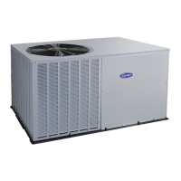
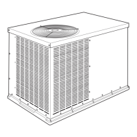
This document provides installation and maintenance instructions for small packaged electric heaters, specifically models in the 5-20kW range, designed for 60 Hz operation. The heaters are intended for use with various HVAC units, including 50ES, 50EZ, 50VG, 50VL, 50VR, 50VT, 604D, 607C, 607E, 704D, 707C, 707E, PA3G, PH3G, PA4G, PH4G, PAD3, PHD3, PAD4, PHD4, WPA4, WPH4, PAR5, and PHR5 series.

Function Description:

These electric heaters are designed to provide supplemental heat within an HVAC system. They integrate with the main unit's control system to energize heating elements based on thermostat calls for heat. The heaters come in various configurations, including single-phase and three-phase, and different voltage and wattage ratings to match specific system requirements. Some models are fused for overcurrent protection, while others are non-fused and rely on external circuit protection.

Important Technical Specifications:

The heaters are available in a range of kilowatt (kW) outputs from 5 kW to 20 kW. Voltage options include 208V, 230V, and 460V. Phase configurations include 1-phase and 3-phase. Frequency of operation is 60 Hz. Amperage ratings vary significantly based on kW and voltage, for example:

  • A 7.5/10.0 kW, 208/240V, 1-phase heater (CPHEATER050A02) has amperage ratings of 36.1A (208V) / 41.7A (240V).
  • A 15.0/20.0 kW, 208/240V, 3-phase heater (CPHEATER059A02) has amperage ratings of 41.4A (208V) / 47.9A (240V).
  • A 10.0 kW, 480V, 3-phase heater (CPHEATER061A02) has an amperage rating of 12.0A. Fuse requirements also vary, with some models using 30A, 50A, or 60A fuses for different circuits. The control voltage for the heater relays is 24V. The maximum duct static pressure for safe electric heater operation is specified in Table 1, with values ranging from 0.30 IN. W.C. (75 pa) to 0.50 IN. W.C. (125 pa) depending on the unit size (024 to 060). Heaters with factory-installed fuses are designed for branch circuit protection by either a fuse or circuit breaker. For other heaters, external branch circuit protection is required. Wiring must comply with NEC and local codes, using a minimum of 75°C copper wire.

Usage Features:

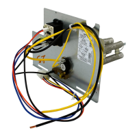
The heaters are designed for both single-point and dual-point electrical connections, offering flexibility in installation depending on the main unit's wiring configuration. Control is achieved via 24VDC control relays, which are energized by a small rectifier board that converts the incoming 24V AC control signal to DC. Some rectifier boards include a time delay feature, providing a delay of approximately 5 seconds (or 8 seconds if a jumper is cut at the factory) after the initial first stage of heat is called. This helps manage power draw and system startup. The heaters are listed for installation only in specific models as detailed in Table 2, ensuring compatibility and safe operation. Schematic diagrams are provided for both fused and non-fused heater configurations, illustrating the wiring for control, power, and field connections. These diagrams are crucial for correct installation and troubleshooting. Identification labels and warning labels are included to ensure proper marking and safety awareness during and after installation.

Maintenance Features:

Regular checks for loose terminal connections are recommended as part of maintenance. Verification of adequate fuse and circuit breaker short circuit interrupting ratings is essential. The document outlines troubleshooting steps for common issues:

  • Fuses: If a malfunction interrupts power, fuses should be checked and replaced after identifying the cause of failure.
  • Limit Switch: If the heating elements are not energized due to a limit switch malfunction, the switch should be replaced.
  • Contactor: If the heater fails to energize due to a faulty contactor, the contactor should be replaced. Attempts to replace only the coil or dress contacts are not recommended. The heater door, which provides access to the control box, is designed for easy opening (for fused models) to facilitate maintenance and inspection. The electrical heater wiring label and schematic are located inside the unit panel or on the lid door for easy reference during servicing. The design allows for trained and qualified personnel to perform installation, repair, and service, emphasizing safety precautions such as turning off main power, locking out switches, and wearing appropriate personal protective equipment.

Carrier 50VG A Series Specifications

General IconGeneral
BrandCarrier
Model50VG A Series
CategoryElectric Heater
LanguageEnglish

Related product manuals