EasyManua.ls Logo

Carrier KFCEH3101C15 - User Manual

Carrier KFCEH3101C15
12 pages
To Next Page IconTo Next Page
Loading...
NOTE: Read the entire instruction manual before starting the installation.
This symbol indicates a change since the last issue.
SAFETY CONSIDERATIONS
Installing and servicing heating and air conditioning equipment can be hazardous due to system pressures and electrical components. Only trained
personnel should install or service heating and air conditioning equipment.
Untrained personnel can perform basic maintenance functions such as cleaning coils, or cleaning and replacing filters. All other operations should
be performed by trained service personnel. When working on heating and air conditioning equipment, observe precautions in the literature, on tags,
and on labels attached to the unit.
Follow all safety codes. Wear safety glasses and work gloves. Have a fire extinguisher available.
Recognize safety information. This is the safety-alert symbol
.
When you see this symbol on the unit and in instructions or manuals, be alert to the potential for personal injury.
Understand the signal words DANGER, WARNING, CAUTION, and NOTE. These words are used with the safety-alert symbol. DANGER
identifies the most serious hazards which will result in severe personal injury or death. WARNING signifies hazards which could result in personal
injury or death. CAUTION is used to identify unsafe practices which would result in minor personal injury or product and property damage. NOTE
is used to highlight suggestions which will result in enhanced installation, reliability, or operation.
WARNING: Before beginning any installation or modification, be sure the main electrical disconnect switch is in the
OFF position. Tag the disconnect switch with a suitable warning label. Electrical shock can cause personal injury or death.
Fig. 1—Installation of 18-, 24-, and 30-kw Model Heaters
A90154
MULTI-CIRCUIT
GROUND LUG
TERMINAL
BLOCK
SINGLE-CIRCUIT
GROUND LUG
ADAPTER PLATE
(MUST BE REMOVED WHEN
INSTALLING LARGE HEATER)
FUSE BLOCK
(24- AND 30-KW)
FUSE COVER
(OMITTED ON 18-KW)
CLIP LATCH
Installation Instructions
KFCEH
Electric Heater
Packages
Form: AG-FCEH-09 Cancels: AG-FCEH-08 Printed in U.S.A. 4-03 Catalog No. 63FC-EH7
Question and Answer IconNeed help?

Do you have a question about the Carrier KFCEH3101C15 and is the answer not in the manual?

Carrier KFCEH3101C15 Specifications

General IconGeneral
BrandCarrier
ModelKFCEH3101C15
CategoryElectric Heater
LanguageEnglish

Summary

Safety Considerations

Introduction

Installation Procedures

Procedure 1: Install Electric Heater Assembly

Steps for installing the electric heater assembly into the fan coil unit, including safety precautions.

Procedure 2: Attach Fuse Box or Circuit Breaker Box

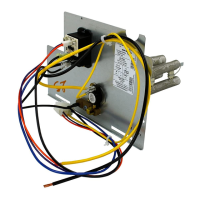
Instructions for mounting the fuse box or circuit breaker box to the fan coil unit.

Procedure 3: Electrical Connections

Guidelines for making electrical connections for the heater, including wiring harnesses and codes.

Power Connections

Details on connecting power to the heater, covering different heater types and circuits.

Ground Connections

Important safety information and steps for ensuring proper grounding of the unit.

Fan Speed Selection for FA, FB, FC, FH, FX, PF1 MNB018-070

Instructions on how to select and adjust motor speed taps on specific fan coil models.

FK4, FE4, FV4, 40 FK, PF1 MNB071 Fan Coil Specifications

Reference to tables for minimum CFM and airflow delivery for specific fan coil models.

Procedure 4: Circuit Breaker Conversion for Downflow

Steps to convert a circuit breaker for downflow applications, including wiring and mounting.

Procedure 5: Attach Wiring Diagram and Rating Label

Guidance on attaching the correct wiring diagram and rating labels to the fan coil unit.

Procedure 6: Verify Installation

Final checks after installation to ensure proper wiring, connections, and cover placement.

Related product manuals