WASHABLE
FILTER
RETAINER
SPRmNG
A00217
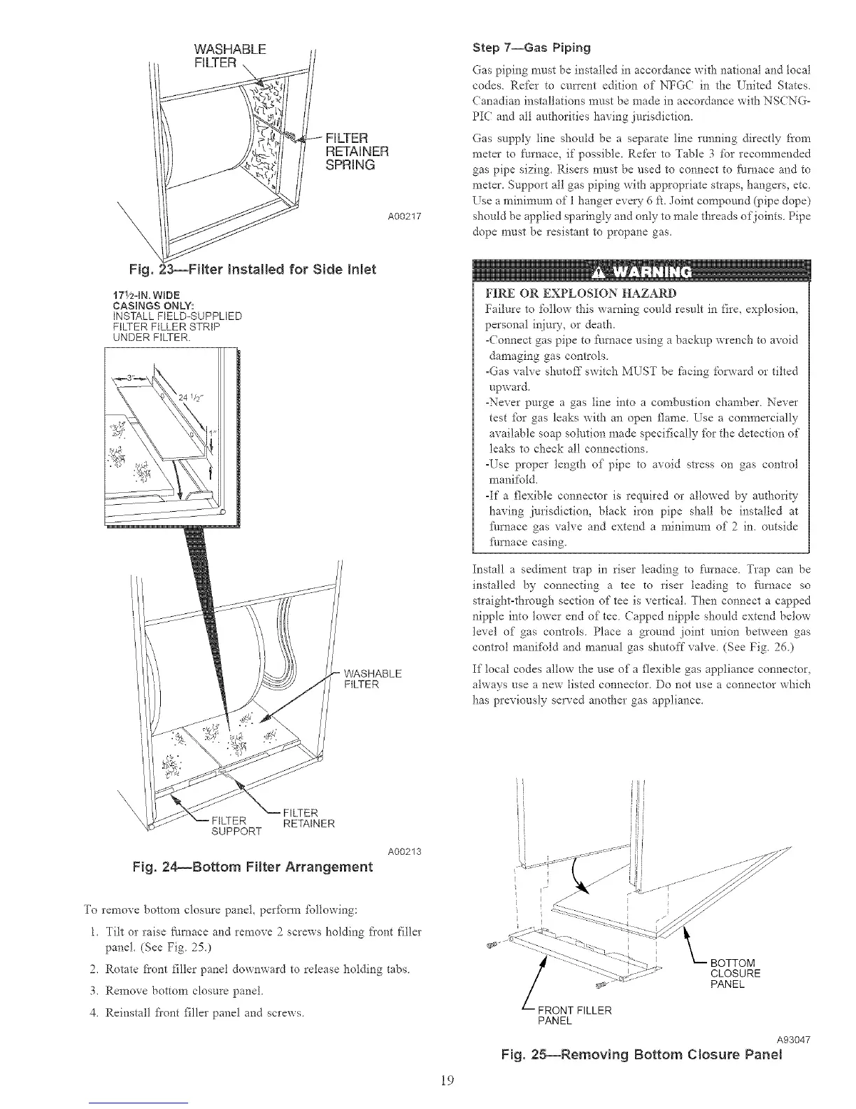
Fig. 23--Filter Installed for Side Inlet
171/2-1N.WmDE
CASINGS ONLY:
INSTALL FELD-SUPPLED
FILTER FILLER STRIP
UNDER FILTER.
WASHABLE
FILTER
Step 7--Gas Piping
Gas piping nrust be installed in accordance with national and local
codes. Refer to cmTent edition of NFGC in the United States.
Canadian installations must be made in accordance with NSCNG-
PIC and all authorities having jurisdiction.
Gas supply line should be a separate line running directly from
meter to furnace, if possible. Ret'_r to Table 3 for recommended
gas pipe sizing. Risers must be used to connect to ftmaace and to
meter. Support all gas piping with appropriate straps, hangers, etc.
Use a minimum of I hanger ever?- 6 ft. Joint compound (pipe dope)
should be applied sparingly and only to male threads of joints. Pipe
dope must be resistant to propane gas.
FIRE OR EXPLOSION HAZARD
Failure to follow this warning could result in fire, explosion,
personal irtim%or death.
-Connect gas pipe to [:m'nace using a backup wrench to avoid
damaging gas controls.
-Gas valve shutoff switch MUST be Pacing fop.yard or tilted
upward.
-Never purge a gas line into a combustion chamber. Never
test fbr gas leaks with an open flame. Use a commercially
available soap solution made specifically fbr the detection of
leaks to check all connections.
-Use proper length of pipe to avoid stress on gas contlol
manifold.
-If a flexible connector is required or allowed by aud-_ority
having jurisdiction, black iron pipe shall be installed at
Nmace gas valve and extend a minimum of 2 in. outside
Nmace casing.
Install a sediment trap in riser leading to tl_rnace Trap can be
installed by connecnng a tee to riser leading to ilu_ace so
stlaight-through section of tee is vertical Then connect a capped
nipple into lower end of tee Capped nipple should extend below
level of gas controls. Place a ground joint union between gas
contlol manifold and manual gas shutoff valve (See Fig. 26)
If local codes allow d_e use of a flexible gas appliance connector.
always use a new listed connector. Do not use a connector which
has previously served another gas appliance.
\\\
\
SUPPORT
FILTER
RETAINER
Fig. 24_Bottom Filter Arrangement
A00213
To remove bottom closure panet, per%tin %llowing:
1. Tilt or raise filmace and remove 2 screws holding fi'ont filler
panel. (See Fig. 250
2. Rotate front filler panel downward to release holding tabs.
3. Remove bottom closure panel.
4. Reinstall fiont filler panel and screws.
19
li
tl
i ¸¸_
BOTTOM
CLOSURE
PANEL
FRONT FILLER
PANEL
A93047
Fig. 25--Removing Bottom Closure Panel

 Loading...


