-->
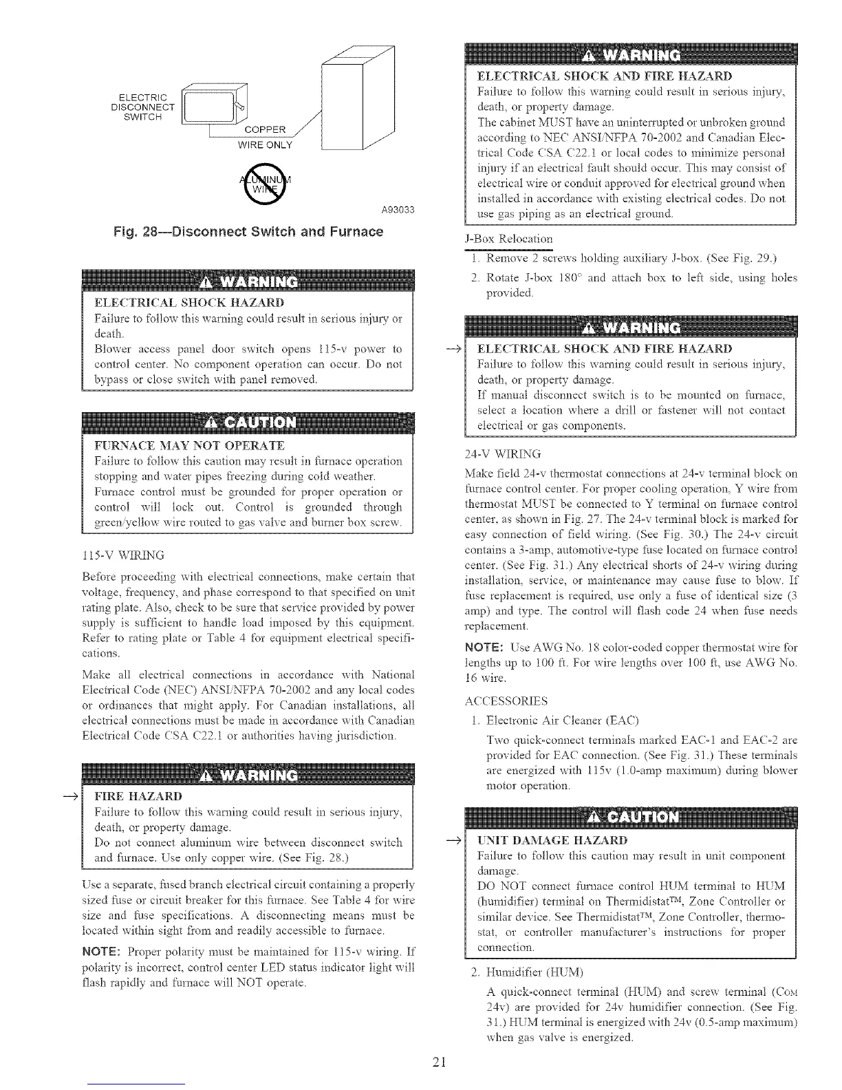
ELECTRIC
DISCONNECT
SWITCH
®
A93033
Fig. 28--Disconnect Switch and Furnace
ELECTRICAL SHOCK HAZARD
Failure to follow this warning could result in serious injury or
death.
Blower access panel door switch opens l15=v power to
control center No component operation can occur Do not
bypass or close switch with panel removed
FURNACE MAY NOT OPERATE
Failure 6o fbllow this caution may result in furnace operation
stopping and water pipes freezing during cold weather.
Furnace control must be grounded for proper operation or
control will lock out. Control is grounded through
green yellow wire routed to gas valve and burner box screw
115-V WIRING
Before proceeding with electrical connections, make certain that
voltage, fiequency, and phase con'espond to d-_at specified on unit
rating plate Also, check to be sure that service provided by power
supply is sufficient to handle toad imposed by this equipment.
Re_kr to rating plate or Table 4 for equipment electrical specifi-
cations.
Make all electrical connections in accordance with National
Electrical Code (NEE) ANSIiNFPA 70°2002 and any local codes
or ordinances that might apply For Canadian installations, all
electrical connections must be made in accordance with Canadian
Electrical (:ode CSA (722.1 or authorities having jurisdiction.
FIRE HAZARD
Failure to _bllow this warning could result in serious injury,
death, or property damage.
Do not connect aluminum wire between disconnect switch
and f_/rnace. Use only copper wire (See Fig. 28)
"Use a separate, fused branch electrical circuit containing a properly
sized fuse or circuit breaker for this furnace See Table 4 _k_rwire
size and filse specifications. A disconnecting means must be
located within sight fiom and readily accessible to furnace
NOTE: Proper polarity must be maintained for 115-v wiring. If
polarity is incorrect, control center LED status indicator light will
flash rapidly and I:umace will NOT operate.
-->
-->
2i
ELECTRICAL SHOCK AND FIRE HAZARD
Failure to follow this warning could result in serions inju U,
death, or property damage.
The cabinet MUST have an uninterrupted or unbroken ground
according to NEC ANSI NFPA 70°2002 and Canadian Elec=
tdcal (7ode CSA (22.1 or local codes to minimize personal
injm T if an electrical fhult should occur. This may consist of
electrical wire or condtlit approved for electrical ground when
installed in accordance with existing electrical codes. Do not
use gas piping as an electrical ground.
J=Box Relocation
1. Remove 2 screws holding auxiliary- J=box. (See Fig. 29.)
2 Rotate J-box 180 _>and attach box to left side, using holes
provided
ELECTRICAL SHOCK AND FIRE HAZARD
Failure to follow this warning could result in serions inju W,
death, or property damage
If manual disconnect switch is to be mounted on fimaace,
select a location where a drill or Pastener will not contact
electrical or gas components.
24-V WIRING
Make field 24-v them_ostat connections at 24°v terminal block on
furnace control center For proper cooling operation, Y wire from
thermostat MUST be connected to Y terminal on [ku_aace control
center, as shown in Fig. 27. The 24=v terminal block is marked fbr
easy connection of field wiring. (See Fig 30.) The 24-v circuit
contains a 3=amp, automotive=type fuse located on fk/rnace control
center (See Fig. 31) Any electrical shorts of 24=v wiring dnring
installation, service, or maintenance may cause litse to blow If
fuse replacement is required, use only a fuse of identical size (3
amp) and type The control will flash code 24 when _k/se needs
replacement
NOTE: Use AWG No 18 color-coded copper them_ostat wire fbr
lengths up to 100 ft For wire lengths over 100 _, use AWG No.
1d wire.
ACCESSORIES
1 Electronic Air Cleaner (EAC)
Two quickoconnect terminals marked EAC-I and EA(=2 are
provided _br EAC connection. (See Fig. 31 ) These tem_inals
are energized with 115v (i 0=amp maximnm) during blower
motor operation.
UNIT DAMAGE HAZARD
Failure to follow this caution may result in unit component
damage
DO NOT connect f_arnace control HUM terminal to HI_M
(humidifier) terminal on Thermidistat TM, Zone Controller or
similar device. See Thermidistat TM, Zone (ontloller, thernao=
stat, or controller manu_itcturer's instructions for proper
connection,
2 Humidifier (HUM)
A quick°connect terminal (HUM) and screw terminal (Cox1
24v) are provided for 24v humidifier connection (See Fig.
31,) HUM tem_inal is energized with 24v (0 5-amp n_axin_un_)
when gas valve is energized,

 Loading...


