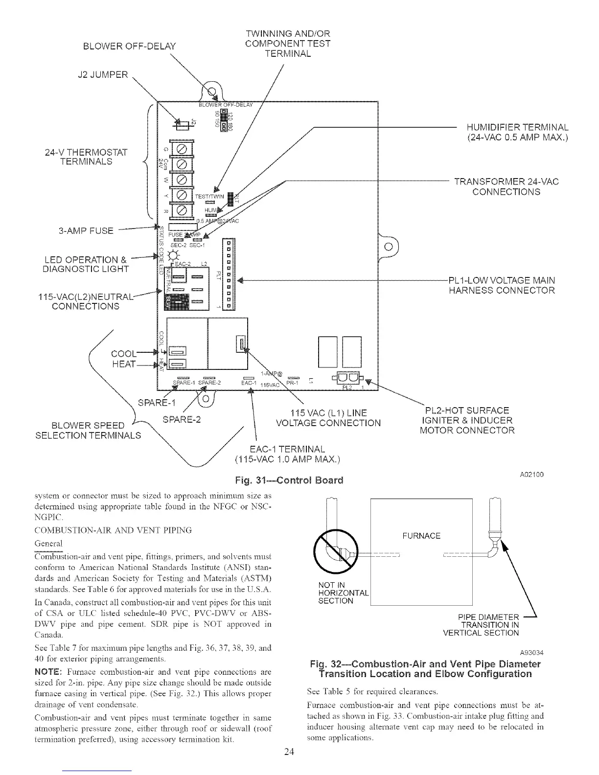
BLOWER OFF-DELAY
J2 JUMPER
TWiNNiNG AND/OR
COMPONENT TEST
TERMINAL
24-V TH ERMOSTAT
TERMINALS
3-AMP FUSE
LED OPERATION &
DiAGNOSTiC LIGHT
115-VAC(L2)N EUTRAL --'11
CONNECTIONS
SEC-2 8EC-1
HUMiDIFiER TERMINAL
(24-VAC 0.5 AMP MAX.)
TRANSFORMER 24-VAC
CONNECTIONS
ob
PL1-LOW VOLTAGE MAiN
HARNESS CONNECTOR
SELECTION TERMINALS
PL2-HOT SURFACE
VOLTAGE CONNECTION IGNITER & INDUCER
_./ EAC-1 TERMINAL
MOTOR CONNECTOR
15AiAC 1.0 AMP MAX.)
Fig. 31--Control Board
A02100
system or connector must be sized to approach minimum size as
detem_ined using appropriate table fbund in the NFG( or NSC°
NGPIC.
COMBUSTION=AIR AND VENT PIPING
General
Combustion°air and vent pipe, fittings, primers, and solvents must
confom_ to American National Standards Institute (ANSI) stan=
dards and American Socie w for Testing and Materials (ASTM)
standards See Table (5fbr approved materials fPr use in the U.SA
In (anada, constluct all combustion-aft and vent pipes fbr this unit
of (SA or ULC listed schedule40 PV(, PVC°DWV or ABS°
DWV pipe and pipe cement SDR pipe is NO7 approved in
( anada.
(
NOT IN
HORIZONTAL
SECTION
FURNACE
TRANSITION IN
VERTICAL SECTION
See Table 7 for maximum pipe lengths and Fig. 36, 37, 38, 39, and
40 fbr exterior piping an'angements
NOTE: Fm'nace combustion°air and vent pipe connections are
sized fbr 2-in. pipe. Any pipe size change should be made outside
furnace casing in vertical pipe. (See Fig. 320 This allows proper
drainage of vent condensate.
Combustion=air and vent pipes must terminate together in same
atmospheric pressure zone, either through roof or sidewall (roof
termination prefBrred), using accessory tem_ination kit.
24
A93034
Fig. 32--Combustion-Air and Vent Pipe Diameter
Transition Location and Elbow Configuration
See Table 5 %r required clearances
Furnace combustion-air and vent pipe connections must be at-
tached as shown in Fig. 33 (ombustion=air intake plug fitting and
inducer housing alternate vent cap may need to be relocated in
some applications.

 Loading...


