HEATPI_MPMODE
Wheninstalledwithaheatpump,thefurnacecontrolautomatically
changesthetimingsequencetoavoidlongblowerofttimesduring
demanddefi'ostcycles.WhentheR-to=W=and-YorR=to=W-and=
Y-and-GcircuitsareenergizedthefurnacecontrolCPUwill
continuetoturnontheblowermotorBLWMatHEATspeed,and
beginaheatingcycle.TheblowermotorBLWMwillremainon
untiltheendoftheprepurgeperiod,thenshutofffor24 seconds
then come back on at HEAT speed. When the W input signal
disappears, the filrnace control begins a normal inducer postrpurge
period and the blower switches to COOL speed after a 3 second
delay. If d_e R-to-W-and-Y-and-G signals disappear at d_e same
time, the blower motor BLWM will remain on fbr the selected
blower-OFF delay period. If the R-to-W-and-Y signals disappear,
leaving the G signal, the blower motor BLWM will continue
running the blower motor BLWM at HEAT speed after the
selected blower-OFF delay period is completed.
Control initiates a 90-sec blower only on period beibre starting
another heat pump cycle if there is a power interruption. Anytime
conkol senses false flame, contlol locks out of heating mode. This
reaction occurs because control ignores W input due to fitlse flame
signal and, as a result, sees only Y input and goes into cooling
mode blower off delay. All other control ffmctions remain in
standard fbrmat.
NOTE: EAC-1 terminal is energized whenever blower operates.
HUM terminal is only energized when gas valve is energized.
COMPONENT TEST
NOTE: The fhrnace control component test allows all compo-
nents to run for a short time: except the gas valve and humidifier
terminal HUM are not energized for safety reasons. The EAC-1
terminal is energized when the blower is energized. This ftamre
helps diagnose a system problem in case of a component failure.
The component test fbature will not operate if any them_ostat
signal is present at the control and not until all time delays are
completed.
NOTE: Record the status code BEFORE opening the blower
access door and befbre shutting offpower to the fhrnace. Opening
the blower access door wil! open the blower door switch and shut
off power within the fhrnace. When power to the furnace is shut
offby either method, the status code will be lost because the code
A99118
Fig. 48--Inducer Housing Orain Cap
38
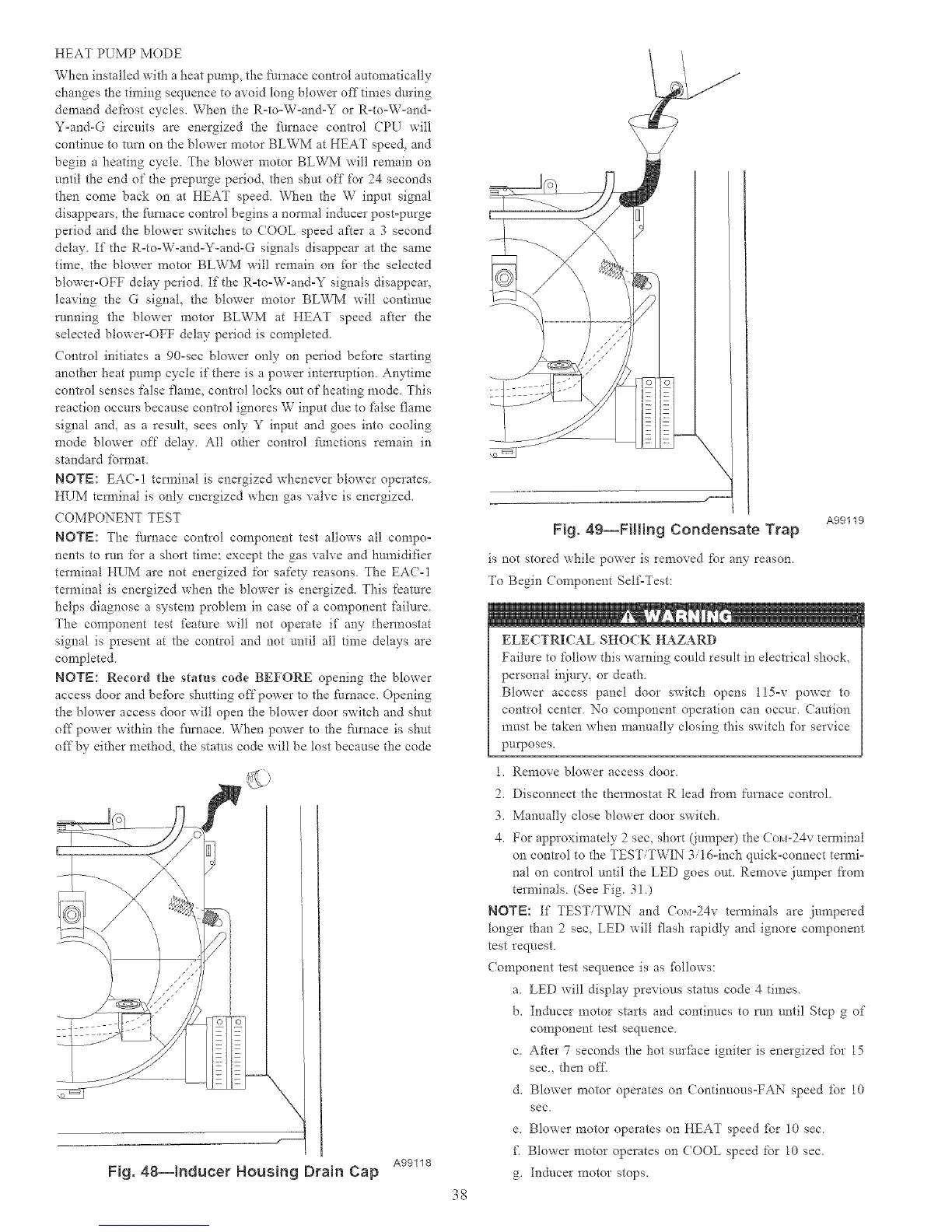
A99119
Fig. 4g--Filling Condensate Trap
is not stored while power is removed fbr any reason.
To Begin Component Self'Test:
ELECTRICAL SHOCK HAZARD
Failure to fPllow this warning could result in electrical shock,
personal injury, or death.
Blower access panel door switch opens l15-v power to
contlol center No component operation can occur. Caution
must be taken when manually closing this switch for service
purposes.
1. Remove blower access door.
2. Disconnect the thermostat R lead fi'om furnace control.
3. Manually close blower door switch.
4. For approximately 2 sec, short (jumper) the Co_i-24v terminal
on control to the TEST/TWIN 3/1 d-inch quick-connect termi-
nal on control until the LED goes out. Remove jumper ti'om
terminals. (See Fig. 3!.)
NOTE: If TEST/TWIN and Co_,i=24v terminals are jumpered
longer than 2 sec, LED will flash rapidly and ignore component
test request.
Component test sequence is as fbllows:
a. LED will display previous status code 4 times.
b. Inducer motor starts and continues to run until Step g of
component test sequence.
c. Afier 7 seconds the hot surface igniter is energized for 15
sec., then off..
d. Blower motor operates on Continuous-FAN speed fbr 10
sec,
e. Blower motor operates on HEAT speed fbr 10 sec.
f_ Blower motor operates on COOL speed tbr 10 sec.
g. Inducer motor stops.

 Loading...


