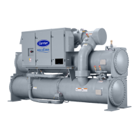
Fig. 18 — Cooler/Discharge Pipe Assembly Removal (Unit with R Compressor Shown)
1—Suction Elbow (Unbolt) 11 — VFD Cooling Drain Line
2—Vaporizer Vent Line (Unbolt) 12 — Oil Reclaim Line (Cut)
3—Motor Cooling Line (Unbolt) 13 — Vaporizer Hot Gas Return Line (Cut)
4—Motor Cooling Drain Line (Cut) 14 — Discharge Isolation Valve (Optional)
5—Tubesheet Mounting Bracket 15 — Condenser Relief Valves
6—Bearing Oil Drain Line 16 — Discharge Temperature Sensor
7—Support Plate 17 — Discharge Pipe Assembly Relief Valve (Unscrew)
8—In-Line Economizer Orifice Plate 18 — Discharge Pressure Sensor
9—Cooler Liquid Feed Line (Unbolt) 19 — Discharge Pressure Switch
10 — Hot Gas Bypass Line (Cut)

 Loading...


