Do you have a question about the Carrier Base Series and is the answer not in the manual?
Visual representation of electrical connections between components and power supply.
Functional diagram illustrating circuit logic and component interconnections.
Procedure for charging the unit with R-410A refrigerant using subcooling method.
Table correlating required liquid line temperature with subcooling for cooling only.
Explanation of diagram symbols, important notes, and safety cautions.
Illustrates wiring for 2-1/2 to 5 ton, 208/230-3 and 3 to 5 ton, 460/3 units.
Functional circuit diagram for 2-1/2 to 5 ton, 208/230-3 and 3 to 5 ton, 460/3 units.
Details on refrigerant charging, notes, and cautions for specific models.
Wiring connections for the 3-5 ton, 575/3 model air conditioner.
Functional circuit diagram for the 3-5 ton, 575/3 model air conditioner.
Refrigerant charging, notes, and cautions specific to 575/3 units.
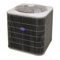
The 24ABB3 Base T™ Series Air Conditioner with Puron® is a robust and efficient outdoor unit designed for residential and light commercial cooling applications. It operates with R-410A refrigerant and is available in 1-1/2 to 5 nominal tons, with single and three-phase electrical configurations. The unit's primary function is to provide reliable cooling by transferring heat from the indoor space to the outdoors.
At its core, the 24ABB3 air conditioner works by circulating refrigerant between an indoor coil (evaporator) and an outdoor coil (condenser), facilitated by a compressor and an outdoor fan motor. The compressor, a key component, pressurizes the refrigerant, causing it to absorb heat from the indoor air and release it to the outdoor air. The outdoor fan motor assists in dissipating this heat by drawing air over the condenser coil.
The unit incorporates several control and safety features to ensure optimal performance and protection. A contactor (CONT) is used to switch the main power to the compressor and outdoor fan motor, controlled by signals from the indoor thermostat. For single-phase units, a start capacitor (CAP) and start relay (SR) may be employed to provide the necessary torque for the compressor to begin operation, especially under heavy loads. A start thermistor (ST) can also be used in conjunction with the start capacitor for improved starting characteristics.
Safety mechanisms are integrated to prevent damage to the compressor and other components. A high-pressure switch (HPS) monitors the refrigerant pressure on the high-side of the system and will shut down the unit if pressure exceeds safe limits, indicating potential issues like a restricted condenser coil or overcharge. Conversely, a low-pressure switch (LPS) monitors the low-side pressure, shutting down the unit if it falls too low, which could indicate a refrigerant leak or restricted evaporator coil.
A compressor time delay (CTD) is included to prevent rapid cycling of the compressor. This delay ensures that the compressor remains off for a minimum of three minutes between cycles, allowing pressures to equalize between the high and low sides of the system. This equalization is crucial for reducing the starting load on the compressor and extending its lifespan.
For units operating in colder climates, a crankcase heater (CH) may be present. This heater warms the compressor oil during off-cycles, preventing refrigerant migration to the compressor crankcase, which can dilute the oil and lead to compressor damage upon startup. A crankcase heater switch (CHS) controls the operation of this heater.
Three-phase units include a Phase Rotation Monitor (PRM) with an LED indicator. This monitor is a critical safety feature that ensures the correct phasing of the 3-phase power supply. If the phasing is incorrect, the PRM will prevent the contactor from energizing, thus protecting the compressor from damage due to reverse rotation. The LED indicator provides visual feedback on the power status: off for no 24VAC, on for OK, and flash for a phase problem.
The unit also supports optional accessories like a liquid line solenoid valve (LLS), which can be used to control refrigerant flow to the indoor coil, and a discharge temperature switch (DTS), which monitors the compressor discharge temperature and can shut down the unit if it becomes too high, indicating potential overheating.
The 24ABB3 is designed for straightforward integration with an indoor thermostat, typically a cooling-only type. The wiring diagrams provide clear instructions for connecting the outdoor unit to the indoor thermostat and the external power supply. For systems with a transformer in the indoor section, specific guidance is given for connecting the grounded side to the BRN/YEL lead.
Charging the unit with R-410A refrigerant is a critical usage feature, and detailed instructions are provided for the subcooling charging method. This method is recommended when the outdoor ambient temperature is between 70°F and 100°F, and the indoor temperature is between 70°F and 80°F, with a line set less than 80 feet. The procedure involves measuring the liquid service valve pressure and the liquid line temperature near the outdoor coil using an accurate gauge and thermistor-type or electronic thermometer. The required subcooling temperature is referenced from the unit's rating plate. If the liquid line temperature is higher than indicated for a specific pressure, refrigerant should be added in liquid form using a flow-restricting device into the suction service port. Conversely, if the temperature is lower, refrigerant should be recovered. A tolerance of +/- 3°F is allowed for the temperature readings.
The unit's design emphasizes safe operation, with warnings against overcharging the system, which can lead to compressor damage. It is factory charged for most systems with matched coils and tubing up to 15 feet. For longer line lengths or specific indoor air flow rates, users are directed to the Product Data Literature for guidance on checking refrigerant charge for maximum efficiency.
Maintenance aspects are primarily focused on ensuring proper electrical connections and refrigerant charge. The manual stresses the importance of checking all electrical connections inside the control box for tightness. This helps prevent loose connections that could lead to intermittent operation or electrical faults.
In the event of system repair or final disposal, all refrigerant must be relieved and recovered. This involves using all service ports and opening all flow-control devices, including solenoid valves, if present. The manual explicitly prohibits venting refrigerant to the atmosphere, emphasizing the use of approved recovery equipment.
The unit's inherent thermal protection for the compressor and fan motor means these components are designed to shut down automatically if they overheat, providing a layer of self-protection. However, it is crucial not to operate the unit until service valves have been fully opened, as this can cause damage.
The compressor time delay, while a usage feature, also contributes to maintenance by protecting the compressor from wear and tear associated with rapid cycling. Users are reminded not to rapid cycle the compressor and to allow the three-minute off-time for pressure equalization.
For three-phase units, the Phase Rotation Monitor simplifies troubleshooting during installation or maintenance by immediately indicating if the power phasing is incorrect, preventing potential damage to the compressor. If a phase problem is detected, the solution is to simply interchange any two of the three power connections on the field side.
Overall, the 24ABB3 air conditioner is designed for reliable and efficient cooling, with built-in safety features and clear instructions for installation, operation, and maintenance, ensuring long-term performance and user safety.
| Sound Level | Varies by model |
|---|---|
| Refrigerant | R-410A |
| Air Flow (Indoor) | Varies by model |
| Dimensions (Indoor Unit) | Varies by model |
| Dimensions (Outdoor Unit) | Varies by model |
| Weight (Indoor Unit) | Varies by model |
| Weight (Outdoor Unit) | Varies by model |
| Type | Split System |
| Power Supply | 208-230V, 1 Phase, 60Hz |