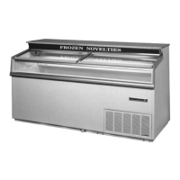
REFRIGERATED UPPER SECTION COMPONENT
IDENTIFICATION & REMOVAL INSTRUCTIONS
1. Defrost Heater Lead Connection 4. Defrost Heater
2. Air Baffle 5. Defrost Heater Retainer Bracket
3. Upper Fin Coil 6. Front Coil Housing Cover Bracket
REMOVAL INSTRUCTIONS:
Disconnect the power
supply before servic-
ing the cabinet.
1. Disconnect the defrost heater
leads located on the lower right-
hand side of the lamp channel –
Figure #1.
2. Remove the air diverter shown as
Figure #2. This will expose the
defrost heater rack which is mount-
ed to the evaporator fin coil. Heater
and rack assembly can now be
removed.
3. Reattach new heater to rack.
NOTE: Last pass of the defrost
heater must lay down in the drain
trough.
4. Reassemble in reverse order.
CAUTION:
11
11
22
22
33
33
44
44
55
55
66
66
32 MAINTENANCE & REPAIR

 Loading...