Do you have a question about the Carrier Comfort 50VL-K and is the answer not in the manual?
Failure to follow this warning could result in personal injury or death. Disconnect power before service.
Failure to relieve system pressure could result in personal injury or death. Recover refrigerant before disposal.
Failure to follow this caution may result in personal injury. Be aware of sharp sheet metal parts and screws.
The unit must be secured to the curb by installing screws through the bottom unit base rails.
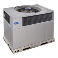
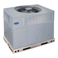
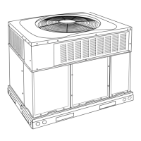
Inspect for shipping damage, check unit model and serial number against shipping papers. Notify if missing.
Install accessory roof curb per instructions. Place unit on a solid, level pad at least 2 inches above grade.
Required clearances to combustible materials and for operation/servicing are listed in tables and diagrams.
Required clearances to combustible materials and for operation/servicing are listed in tables and diagrams.
Details on small/common and large roof curbs, including dimensions, catalog numbers, and installation notes.
WARNING: Rigging and handling can be hazardous. Use trained operators and follow all safety precautions.
Ensure roof support. Provide adequate ventilation and outdoor air. Do not restrict airflow for compressor life.
Maximum allowable difference for unit leveling is 1/4 inch to ensure proper drain function.
WARNING: Never stand beneath rigged units or lift over people. Secure large base units before lifting.
Install a 2-in. condensate trap at the end of the condensate connection for proper drainage.
Install ductwork per NFPA and SMACNA/ACCA standards. Insulate and weatherproof all external ductwork.
Remove horizontal ductcovers to access vertical downflow knockouts. Reinstall covers for air/watertight seal.
Make electrical connections per NFPA 70 and local codes. Use copper conductors only. Check voltage range.
Use #18 AWG wires for thermostat control connections. Use #16 AWG for runs over 100 ft.
Connect low voltage leads from heater to factory control leads. Ensure transformer protection and check fuses.
The transformer is energy-limiting. Check blower fuse on Indoor Fan Board if overload/short occurs.
Table 1 provides unit size, weight, capacity, refrigerant charge, coil, fan, and blower specifications.
Table 1 lists recommended sizes for return-air filters based on unit size and airflow requirements.
WARNING: Never use oxygen for leak testing. Relieve and recover refrigerant before repair.
Check blower motor, compressor, condenser fan, and evaporator fan motors for proper sequence and operation.
Use accurate thermometers and gauge manifold for evaluating unit charge. Refer to charging charts.
CAUTION: Ensure proper airflow for cooling/heating. Check filter and grilles. Adjust blower speed if needed.
Configure for single speed cooling by moving DEHUM jumper to STD and connecting speed tap to LOW.
For dehumidification, move DEHUM jumper to DEHUM and set fan speed taps for cooling and dehumidification.
Table 4 provides CFM and BHP for various unit sizes, speeds, and ESP values for dry coil conditions.
Table 4 continues CFM and BHP data for different unit sizes, speeds, and ESP values for dry coil conditions.
Table 5 shows wet coil pressure drop. Table 7 provides pressure drop for different filter sizes.
Tables 8 and 9 show electric heat pressure drop for small and large cabinets at various static pressures.
Diagram shows high and low voltage connections for a single-phase 208/230V unit with legend.
Ladder diagram illustrates wiring for a single-phase 208/230V unit, including thermostat and electric heat.
Diagram shows high and low voltage connections for a three-phase 208/230V unit with legend.
Ladder diagram illustrates wiring for a three-phase 208/230V unit, including thermostat and economizer.
Diagram shows high and low voltage connections for a three-phase 460V unit with legend.
Ladder diagram illustrates wiring for a three-phase 460V unit, including thermostat and electric heat.
Use superheat charging method based on outdoor temp and indoor wet-bulb temp to determine correct charge.
Inspect air filter monthly. Clean indoor coil, drain pan, blower motor, and electrical connections annually.
WARNING: Disconnect power. Clean accumulated dirt and grease from blower wheel and motor annually.
Inspect and clean outdoor/indoor coils and drain pan annually. Straighten bent fins and remove obstructions.
Inspect electrical controls and wiring annually. Tighten connections and check for signs of damage.
Check for leaks with detector. Test low/high pressure switches for proper operation and continuity.
System uses Puron (R-410A). Compressor is designed for this refrigerant only. Handle with care.
Details on single cylinder rotary compressor design, operation, and heat characteristics for specific units.
Take precautions to protect roofing when servicing to prevent oil damage. Use drip cloths and towels.
Table 10 lists common symptoms, causes, and remedies for compressor, fan, and pressure issues.
Record unit info and verify removal of packing, shipping bolts, filter, level installation, and fan wheel.
Record supply voltage, compressor amps, fan amps, and outdoor/return/supply air temperatures.
Record suction/discharge pressures and temperatures. Verify refrigerant charge using charging charts.
| Brand | Carrier |
|---|---|
| Model | Comfort 50VL-K |
| Category | Air Conditioner |
| Language | English |