F96CTN and G96CTN (Series A): Installation, Start-up, Operating, Service and Maintenance Instructions
Manufacturer reserves the right to change, at any time, specifications and designs without notice and without obligations.
44
A11310A
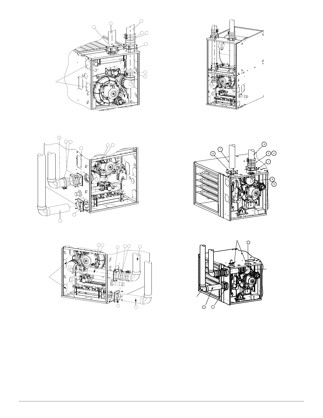
UPFLOW VERTICAL VENT
Fig. 54 – Upflow Configurations (Appearance may vary)
See “Notes for Venting Options”
A11311A
DOWNFLOW LEFT CONFIGURATION
A11312A
DOWNFLOW RIGHT CONFIGURATION
A11313A
DOWNFLOW VERTICAL
Fig. 55 – Downflow Configurations (Appearance may vary)
See “Notes for Venting Options”
A11327A
HORIZONTAL LEFT-VERTICAL VENT CONFIGURATION
A11328A
HORIZONAL LEFT-LEFT VENT CONFIGURATION
1
2
3
4
5
6
7
5
Any other unused
knockout may be used
for combustion air
connection.
1
2
3
4
5
6
7
5
Rotate vent elbow to
required position.
1
2
3
4
5
6
7
5
Rotate vent elbow to
required position.
Any other unused
knockout may be used
for combustion air
connection.
Requires Accessory Internal Vent Kit.
See Product Data for current kit number.
6
4
Alternate combustion air
connection.
Rotate vent
elbow to
required
position.
4
5
Vent Pipe
 Loading...


