FMC5X, FMC5Z: Installation Instructions
Manufacturer reserves the right to change, at any time, specifications and designs without notice and without obligations.
3
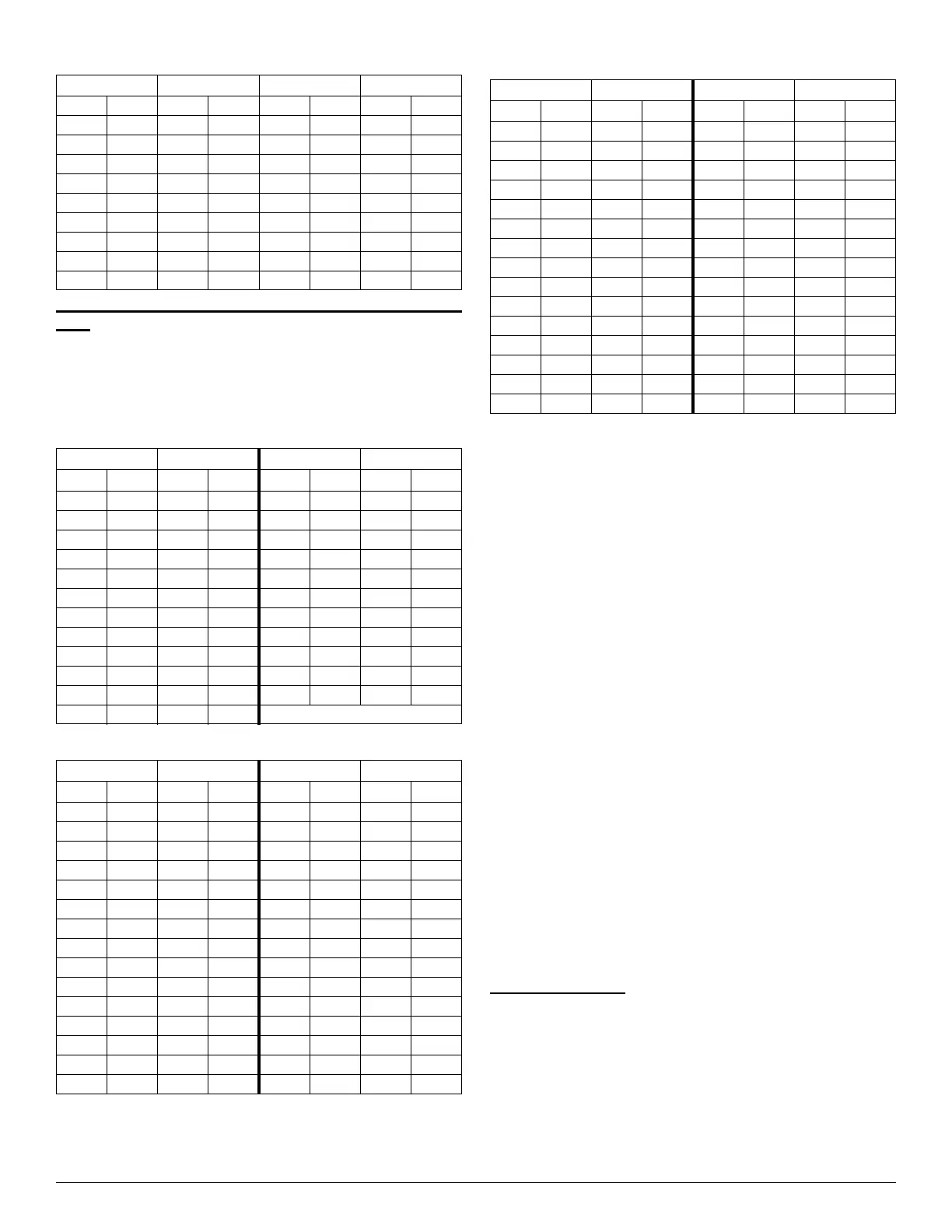
The Maximum Refrigerant Charge and Minimum Room
Area
If the fan incorporated to an appliance is continuously operated or
operation is initiated by a REFRIGERANT DETECTION SYSTEM
with a sufficient CIRCULATION AIRFLOW rate, the maximum
refrigerant charge (Mmax) and the required minimum room area (Amin)
is shown in Table 7 and Table 8.
NOTE: The maximum refrigerant charge of Table 7 or the required
minimum room area of Table 8 is available only if the following
conditions are met: Minimum velocity of 1m/s2, which is calculated as
the indoor unit airflow divided by the nominal face area of the outlet.
And the grill area shall not be deducted. Minimum airflow rate must
meet the corresponding values in Table1-5, which is related to the actual
refrigerant charge of the system (Mc). R-454B refrigerant leakage sensor
is configured.
NOTE: The maximum refrigerant limit described above applies to
unventilated areas. If adding additional measures, such as areas with
mechanical ventilation or natural ventilation, the maximum refrigerant
charge can be increased or the minimum room area can be reduced. If the
R-454B refrigerant leakage sensor is configured for the indoor unit, and
meets the incorporated circulation airflow requirements, the maximum
refrigerant charge or minimum room area can be determined according
to Table 6 or Table 8.
NOTE: If the actual room area, outlet height, and refrigerant charge
amount are not reflected in the above table, more severe cases need to be
considered according to the data in the table.
INSTALLATION
Check Equipment
Unpack unit and move to final location. Remove from carton, avoid
lifting from blower wheels, taking care not to damage unit. Inspect
equipment for damage prior to installation. File claim with shipping
company if shipment is damaged or incomplete. Locate rating plate on
unit. It contains information needed to properly install unit. Check rating
plate to be sure unit matches job specifications.
NOTE: Installation clearance from combustible materials is 0" (0 mm)
from unit and supply-air duct.
Mount Fan Coil
Fan Coil Mounting
Mounting brackets are provided on all four corners of the casing for
attachment of the fan coil to supporting structure. The supporting
structure must be designed to safely support the full weight of the fan
coil. Field supplied washers and bolts capable of supporting the fan coil
load should be used to secure the fan coil to the supporting structure at
the mounting slots.
The fan coil must be mounted level to ensure proper drainage of
condensate. If the supporting structure is not level at the points of fan
coil attachment, then spacers must be used to level the fan coil.
170 19 17-3 7.8 11-5 5.1 0.7 0.08
180 20 17-3 7.8 12-0 5.4 0.6 0.07
190 21 17-3 7.8 12-10 5.7 0.5 0.06
200 22 17-3 7.8 13-5 6.0 0.5 0.06
210 23 17-3 7.8 14-0 6.4 0.4 0.04
220 24 17-3 7.8 14-10 6.6 0.3 0.03
230 26 17-3 7.8 15-5 6.9 0.2 0.02
240 27 17-3 7.8 16-0 7.3 0.1 0.01
250 28 17-3 7.8 16-10 7.5 0.1 0.01
260 29 17-3 7.8 17-5 7.9 0.0 0.00
Table 2 – Maximum Refrigerant Charge
A/TA Mmax A/TA Mmax
ft
2
m
2
lb-oz kg ft
2
m
2
lb-oz kg
40 4 2-10 2.6 160 18 10-10 10.6
50 6 3-5 3.3 170 19 11-5 11.3
60 7 4-0 4.0 180 20 12-0 12.0
70 8 4-10 4.6 190 21 12-10 12.6
80 9 5-5 5.3 200 22 13-5 13.3
90 10 6-0 6.0 210 23 14-0 14.0
100 11 6-10 6.6 220 24 14-10 14.6
110 12 7-5 7.3 230 26 15-5 15.3
120 13 8-0 8.0 240 27 16-0 16.0
130 14 8-10 8.6 250 28 16-10 16.6
140 16 9-5 9.3 260 29 17-5 17.3
150 17 10-0 10.0
Table 3 – Required Minimum Room Area
Mc Amin/Tamin Mc Amin/Tamin
lb-oz kg ft
2
m
2
lb-oz kg ft
2
m
2
4-6 4.4 66.1 7.3 11-0 11.0 165.3 18.4
4-13 4.8 72.7 8.1 11-7 11.4 171.9 19.1
5-4 5.3 79.3 8.8 11-14 11.9 178.5 19.8
5-11 5.7 86.0 9.6 12-5 12.3 185.1 20.6
6-2 6.1 92.6 10.3 12-12 12.8 191.7 21.3
6-9 6.6 99.2 11.0 13-3 13.2 198.4 22.0
7-0 7.0 105.8 11.8 13-10 13.6 205.0 22.8
7-7 7.4 112.4 12.5 14-1 14.1 211.6 23.5
7-15 7.9 119.0 13.2 14-8 14.5 218.2 24.2
8-6 8.4 125.6 14.0 14-15 14.9 224.8 25.0
8-13 8.8 132.2 14.7 15-6 15.4 231.4 25.7
9-4 9.3 138.8 15.4 15-14 15.9 238.0 26.4
9-11 9.7 145.5 16.2 16-5 16.3 244.6 27.2
10-2 10.1 152.1 16.9 16-12 16.8 251.2 27.9
10-9 10.6 158.7 17.6 17-3 17.2 257.9 28.7
Table 1 – (Continued)Minimum Opening Area for Connected
A Mc Mmax Anvmin
Table 4 – Minimum Circulation Airflow
Mc Amin/Tamin Mc Amin/Tamin
lb-oz kg CFM m
3
/h lb-oz kg CFM m
3
/h
4-6 4.4 119 202.3 11-0 11.0 298 506.6
4-13 4.8 131 222.7 11-7 11.4 310 527.0
5-4 5.3 143 243.1 11-14 11.9 322 574.4
5-11 5.7 155 263.5 12-5 12.3 334 567.8
6-2 6.1 167 283.9 12-12 12.8 346 588.2
6-9 6.6 179 304.3 13-3 13.2 358 608.6
7-0 7.0 191 324.7 13-10 13.6 370 629.0
7-7 7.4 203 345.1 14-1 14.1 382 649.4
7-15 7.9 215 365.5 14-8 14.5 394 669.8
8-6 8.4 227 385.9 14-15 14.9 406 690.2
8-13 8.8 239 406.3 15-6 15.4 418 710.6
9-4 9.3 251 426.7 15-14 15.9 430 731.0
9-11 9.7 263 447.1 16-5 16.3 442 751.4
10-2 10.1 275 467.5 16-12 16.8 454 771.8
10-9 10.6 287 487.9 17-3 17.2 466 792.2