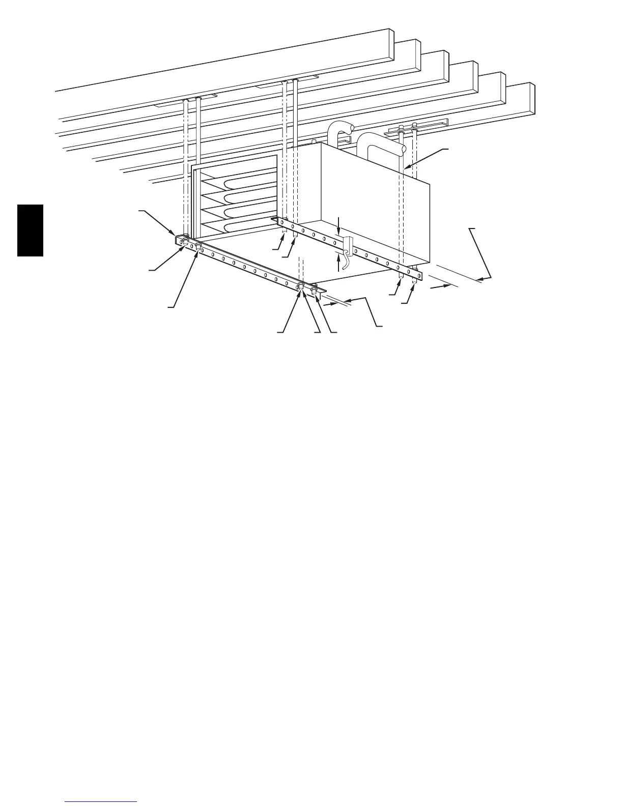
EasyManuals Logo

Carrier INFINITY ICS 58MVC User Manual

Carrier INFINITY ICS 58MVC
60 pages
To Next Page IconTo Next Page
To Previous Page IconTo Previous Page
Page #18 background imageLoading...
Page #18 background image
18
NOTES:
ANGLE
IRON OR
EQUIVALENT
(B)
(A) ROD LOCATION
USING DIMPLE
LOCATORS
(SEE DIMENSIONAL
DWG FOR
LOCATIONS)
13
/
16
-IN. MAX
ALTERNATE SUPPORT
LOCATION FROM BACK
ALTERNATE SUPPORT
LOCATION 4-IN. MIN
8-IN. MAX
3
/
8
-IN. ROD
(A)
(B)
(A)
(B)
(B)
(A)
1. A 1 In. clearance minimum between top of
furnace and combustible material.
2. The entire length of furnace must be
supported when furnace is used in horizontal
position to ensure proper drainage.
(A) PREFERRED ROD LOCATION
(B) ALTERNATE ROD LOCATION
DRAIN
5
3
/
4
3
/
8
-IN. HEX NUT
& WASHER (4)
REQD PER ROD
A93304
Fig. 23 -- Crawlspace Horizontal Application for Direct Vent/2--Pipe Installation and for Ventilated Combustion Air Installation
58MVC

Table of Contents

Other manuals for Carrier INFINITY ICS 58MVC

Questions and Answers:

Question and Answer IconNeed help?

Do you have a question about the Carrier INFINITY ICS 58MVC and is the answer not in the manual?

Carrier INFINITY ICS 58MVC Specifications

Power IconPower
electrical supply voltage115 volts
electrical supply frequency60 Hz
electrical supply phasesingle-phase
Operating Environment IconOperating Environment
fuel gas efficiency92.1 to 95% AFUE
minimum air delivery_ _ _ cfm
external static pressure0.50 in. wc
Weight and Dimensions IconWeight and Dimensions
casing thickness0.030 in
depth_ in.
width_ in.
height_ in.

Related product manuals