7
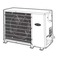
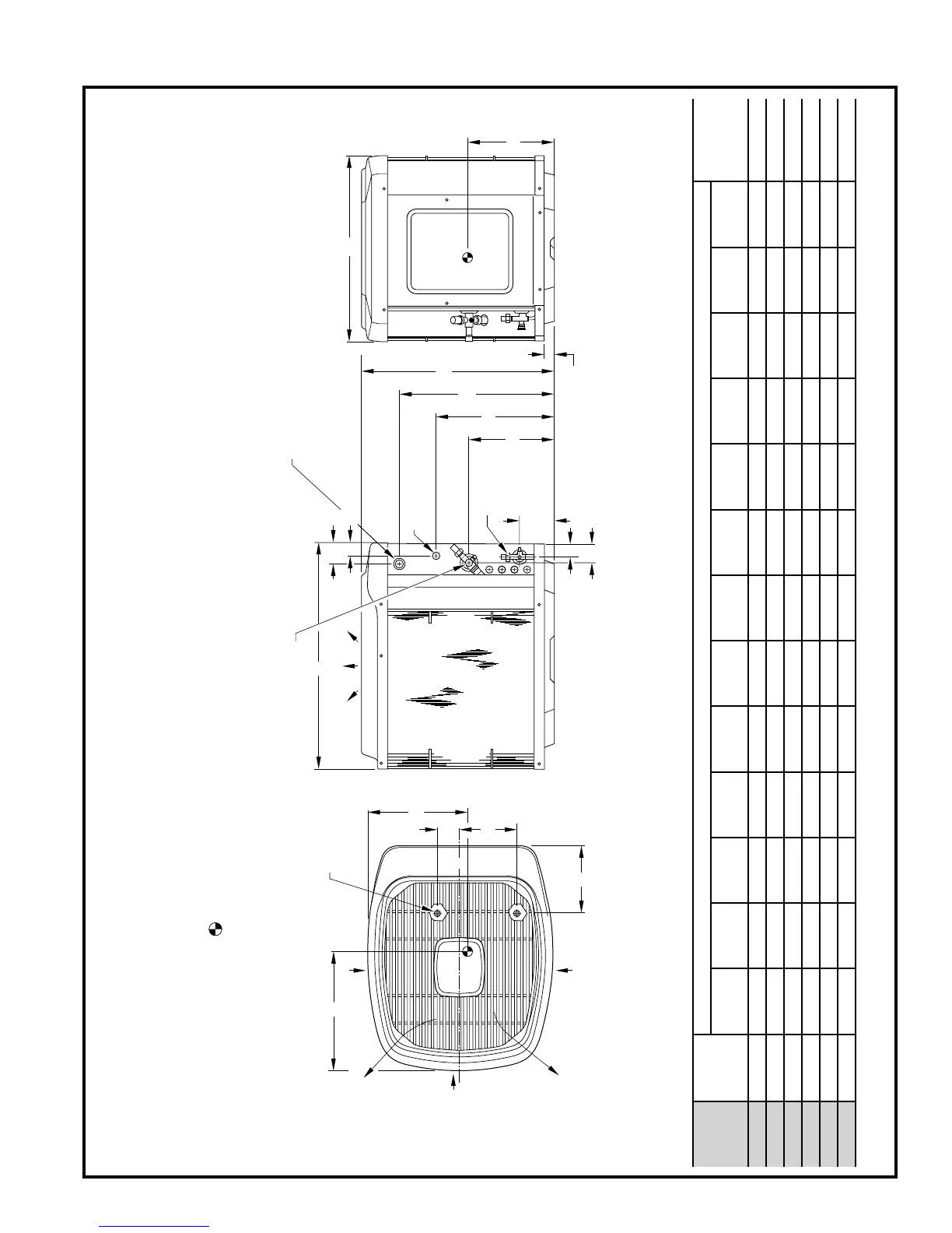
Dimensions
2
1
/2"
1
9
/16"
AIR DISCHARGE
4
3
/16"
3
/8 IN. DIA.
LIQUID LINE
CONN
1
3
/4"
FIELD POWER SUPPLY CONN
7
/8 IN. DIA HOLE WITH
1
1
/8 IN. DIA KNOCKOUT
AND
1
3
/8 IN. DIA KNOCKOUT
10
1
/2"
F
G
N
A
FIELD CONTROL SUPPLY
CONN
7
/8 IN. DIA HOLE
AIR DISCHARGE
AIR DISCHARGE
AIR IN
AIR IN
AIR IN
H DIA VAPOR LINE CONN
3
/8 IN. DIA TIEDOWN
KNOCKOUTS (2)
PLACES IN BASEPAN
B
1
1
/4"
M
ACCESS
PANEL
L
K
C
D
E
J
C
L
1. Allow 30 in. clearance to service side of unit, 48 in. above unit, 6 in.
on one side, 12 in. on remaining side, and 24 in. between units for proper airflow.
Minimum outdoor operating ambient in cooling mode is 55°F (unless low ambient control is used) max 125°F.2.
Series designation is the 13th position of the unit model number.3.
Center of gravity .4.
NOTES:
A97084
DIMENSIONS (IN.)
UNIT
SIZE SERIES
UNIT DIMENSIONS MINIMUM
MOUNTING
PAD
DIMENSIONSABCDEFGHJKLMN
024 34 27-13/16 30 34-15/16 4 9-3/4 15-1/2 21-7/8 5/8 8-3/16 17 19-3/4 13 2-15/16 26 x 32
030 33 27-13/16 30 34-15/16 4 9-3/4 15-1/2 21-7/8 3/4 8-3/16 18-1/2 19-3/4 13 2-15/16 26 x 32
036 33, 34 33-13/16 30 34-15/16 4 9-3/4 21-1/2 27-7/8 3/4 8-3/16 17 19-3/4 15-3/4 2-15/16 26 x 32
042 33 39-13/16 30 34-15/16 4 9-3/4 27-1/2 33-7/8 7/8 8-3/16 17-3/4 19 17-3/4 2-15/16 26 x 32
048 33 39-13/16 30 34-15/16 4 9-3/4 27-1/2 33-7/8 7/8 8-3/16 16-3/4 19-1/2 17-1/4 2-15/16 26 x 32
060 35 39-13/16 30 34-15/16 4 9-3/4 27-1/2 33-7/8 7/8 8-3/16 16-1/2 19 16-3/4 2-15/16 26 x 32