12
STATUS
CODES
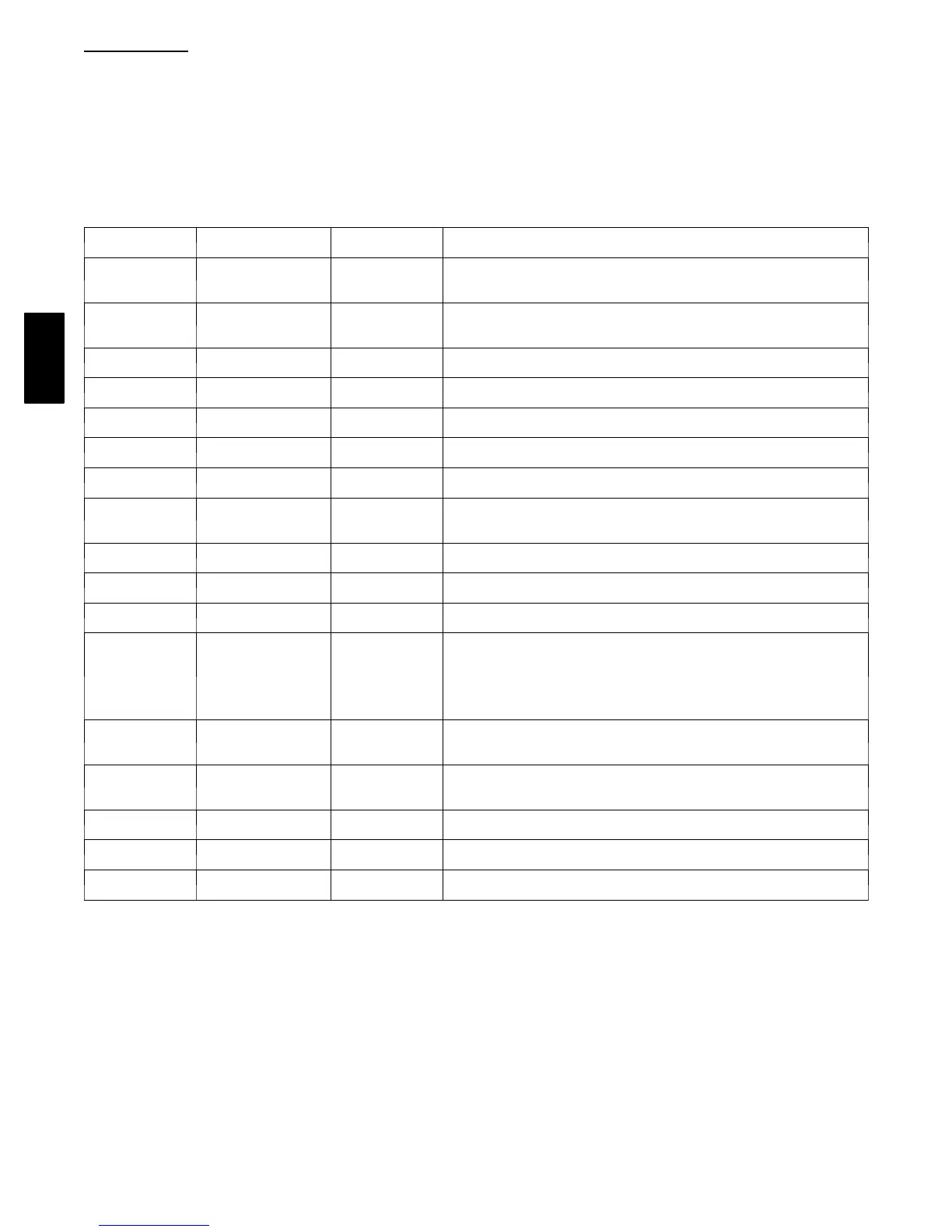
Table 3 shows the status codes flashed by the amber status light.
Most system problems can be diagnosed by reading the status
code as flashed by the amber status light on the control board.
The codes are flashed by a series of short and long flashes of the
status light. The short flashes indicate the first digit in the status
code, followed by long flashes indicating the second digit of the
error code. The short flash is 0.25 second ON and the long flash
is 1.0 second ON. Time between flashes is 0.25 second. Time
between short flash and first long flash is 1.0 second. Time
between code repeating is 2.5 seconds with LED OFF.
Count the number of short and long flashes to determine the
appropriate flash code. Table 3 gives possible causes and actions
related to each error .
Example: 3 short flashes followed by 2 long flashes indicates a
32 code. Table 3 shows this to be low pressure switch open.
Table 3— S tatus Codes
OPERATION FAUL T
AMBER LED
FLASH CODE
Possible Cause and Action
Standby – no
call for unit
operation
None On solid, no flash Normal operation --- 3 thermostat wires or 4 wire Infinity Control
Standby – no
call for unit
operation
None Off
Normal operation --- No call for cooling with 2---wire connection or indoor
unit not powered.
Cooling
Operation
None 1, pause Normal operation
System Communica-
tions Failure
16
Communication with user interface lost. Check wiring to UI, indoor and
outdoor units
High Pressure
Switch Open
31
High pressure switch trip. Check refrigerant charge, outdoor fan opera-
tion and coils for airflow restrictions.
Low Pressure
Switch Open
32 Low pressure switch trip. Check ref rigerant charge and indoor air flow
Control Fault 45
Outdoor unit control board has failed. Control board needs to be
replaced.
Brown Out
(24 v)
46
The control voltage is less than 15.5v for at least 4 seconds. Compressor
and fan operation not allowed until control voltage is a minimum of 17.5v.
Verify control voltage.
Outdoor Air Temp
Sensor Fault
53
Outdoor air sensor not reading or out of range. Ohm out sensor and
check wiring
Outdoor Coil Sensor
Fault
55 Coil sensor not reading or out of range. Ohm out sensor and check wiring
Thermistors out
of range
56
Improper relationship between coil sensor and outdoor air sensor. Ohm
out sensors and check wiring.
Thermal C utout 72
Compressor voltage sensed after start--- up, then absent for 10 consecu-
tive seconds while cooling demand exists. Possible causes are internal
compressor overload trip or loss of high voltage to compressor without
loss of control voltage. The control will continue fan operation and wait
15 minutes to attempt a restart. Fault will clear when restart is successful,
or low voltage power is cycled.
Contactor Shorted 73
Compressor voltage sensed when no demand for compressor operation
exists. Contactor may be stuck closed or there is a wiring error.
No 230V at
Compressor
74
Compressor voltage not sensed when compressor should be starting.
Disconnect may be open or contactor may be stuck open or there is a
wiring error.
Thermal L ockout 82
Thermal cutout occurs in three consecutive cycles. Unit operation locked
out for 4 hours or until 24v power recycled.
Low Pressure Lockout 83
Low pressure switch trip has occurred during 5 consecutive cycles. Unit
operation locked out for 4 hours or until 24v power recycled.
High Pressure
Lockout
84
High pressure switch trip has occurred during 5 consecutive cycles. Unit
operation locked out for 4 hours or until 24v power recycled.
24APA

 Loading...