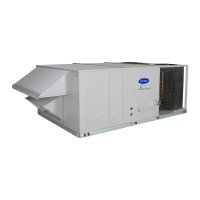
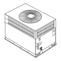
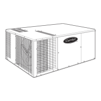
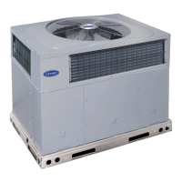
48HC
Single Package Rooftop
Gas Heating/Electric Cooling Unit
with Puronr (R---410A) Refrigerant
Sizes: 17, 20, 24, 28
Installation Instructions
NOTE: Read the entire instruction manual before starting
the installation
TABLE OF CONTENTS
SAFETY CONSIDERATIONS 2....................
INSTALLATION 9...............................
Jobsite Survey 9................................
Step 1 -- Plan for Unit Location 9..................
Roof Mount 9...............................
Step 2 -- Plan for Sequence of Unit Installation 10.....
Curb--Mount Installation 10....................
Pad--Mount Installation 10.....................
Frame--Mount Installation 10...................
Step 3 -- Inspect Unit 10..........................
Step 4 -- Provide Unit Support 10..................
Roof Curb Mount 10.........................
Slab Mount (Horizontal Units Only) 10..........
Alternate Unit Support
(In Lieu of Curb or Slab Mount) 10.............
Step 5 -- Field Fabricate Ductwork 14...............
Step 6 -- Rig and Place Unit 14....................
Positioning on Curb 15.......................
Step 7 -- Horizontal Duct Connection 15............
Step 8 -- Install Outside Air Hood — Factory Option 15..
Step 9 -- Install Flue Hood and Combustion Air Hood 16..
Step 10 -- Install Gas Piping 16....................
Gas Supply Line 16..........................
Factory--Option Thru--Base Connections 18.......
Step 11 -- Install External Condensate Trap and Line 19..
Step 12 -- Make Electrical Connections 19...........
Field Power Supply 19........................
Units without Factory--Installed Disconnect 20....
Units with Factory--Installed Disconnect 20.......
All Units 20................................
Convenience Outlets 20.......................
Factory--Option Thru--Base Connections 22......
Units without Thru--Base Connections 22.........
Field Control Wiring 22.......................
Thermostat 22...............................
Unit without Thru--Base Conversion Kit 22.......
Heat Anticipator Settings 23...................
Transformer Connection
for 208--v Power Supply 23.....................
Humidi--MiZer
R
Control Connections 24..........
Humidi--MiZer -- Space RH Controller 24........
PremierLinkt (Factory Option) 26...............
Supply Air Temperature (SAT) Sensor 29.........
Outdoor Air Temperature (OAT) Sensor 29.......
EconoMi$er2 29.............................
Field Connections 29..........................
Space Sensors 31............................
Connect Thermostat 31.......................
Configure the Unit for Thermostat Mode 31......
Economizer Controls 32........................
Indoor Air Quality (CO
2
)Sensor 32.............
Outdoor Air Quality Sensor 32.................
Space Relative Humidity Sensor or
Humidistat Connections 33....................
Smoke Detector/Fire Shutdown (FSD) 34.........
Filter Status Switch 34........................
Supply Fan Status Switch 34...................
Remote Occupied Switch 34...................
Power Exhaust (output) 34.....................
CCN Communication Bus 35..................
RTU Open Control System 36...................
Supply Air Temperature (SAT) Sensor 39.........
Outdoor Air Temperature (OAT) Sensor 39.......
EconoMi$er2 39.............................