ZONECC3Z(AC/HP)01
Installation and Start-Up Instructions
TABLE OF CONTENTS
Page
SAFETY CONSIDERATIONS ...................................................1
INSTALLATION CONSIDERATIONS....................................1
INTRODUCTION........................................................................1
INSTALLATION......................................................................1-4
• Check Equipment And Job Site ..............................................1-2
• Component Location And Wiring Considerations.....................2
• Install Components......................................................................2
• Install Zone Dampers...............................................................2-4
• Install Barometric Bypass Damper.............................................4
• Install Leaving Air Temperature (LAT) Sensor.........................4
• Install Heat Pump Temperature (HPT) Sensor ..........................4
SYSTEM WIRING...................................................................4-5
• Wire Thermostats ........................................................................4
• Wire Equipment...........................................................................4
• Wire Dampers..............................................................................5
• Wire Remainder...........................................................................5
UNDERSTANDING SYSTEM OPERATION......................6-7
SYSTEM SETUP....................................................................7-10
NOTE: Read the entire instruction manual before starting the
installation.
SAFETY CONSIDERATIONS
Improper installation, adjustment, alteration, service, maintenance,
or use can cause fire, electrical shock, or other conditions which
may cause personal injury or property damage. Consult a qualified
installer, service agency or your distributor or branch for informa-
tion or assistance. The qualified installer or agency must use
factory-authorized kits or accessories when modifying this prod-
uct. Refer to the individual instructions packaged with the kits or
accessories when installing.
Follow all safety codes and wear safety glasses. Have fire
extinguisher available. Read these instructions thoroughly and
follow all warnings or cautions attached to the unit. Consult local
and state building codes and Sheet Metal and Air Conditioning
National Association (SMACNA) for special installation require-
ments.
Recognize safety information. This is the safety-alert symbol
.
When you see this symbol on the unit or in instructions and
manuals, be alert to the potential for personal injury.
Understand the signal words DANGER, WARNING, and CAU-
TION. These words are used with the safety-alert symbol. DAN-
GER identifies the most serious hazards which will result in severe
personal injury or death. WARNING signifies hazards which
could result in personal injury or death. CAUTION is used to
identify unsafe practices which would result in minor personal
injury or product and property damage. NOTE is used to highlight
suggestions which will result in enhanced installation, reliability,
or operation.
INSTALLATION CONSIDERATIONS
Before the actual installation of a zoning system can begin,
decisions need to be made to determine the number and location of
zones. This affects duct and damper selections.
This instruction covers the physical installation and start up of the
Carrier 3-Zone system. Use this instruction to guide the actual
installation process after all the air side decisions have been made.
1. Install in non-condensing areas with ambients between 32°F
and 158°F.
2. A TXV is required on the indoor coil when used with all
residential split system equipment.
3. A separate transformer is not needed to power the 3-Zone
system. Up to five dampers may be used in each zone by
electrically connecting them in parallel.
4. Load calculations must be performed for each zone’s peak
demand. Size each zone duct for at least its peak demand plus
25%. Size equipment for the building block load, not the sum
of zone peak demands. It is important that the equipment not
be oversized.
5. When only two zone operation is needed, any two of the three
zone connections may be used. There is no inherent priority
dependent on zone number.
UNIT DAMAGE HAZARD
Failure to follow this caution may result in unit damage.
TXV on indoor coil is required with all residential split
system equipment.
INTRODUCTION
The Carrier 3-Zone system allows the air conditioning and heating
equipment to control temperatures in 3 distinct spaces or zones
within a building. Each zone has independent temperature settings
controlled by a conventional thermostat.
There are two distinct controllers:
• ZONECC3ZAC01 - Single Stage Heat / Single Stage Cool
using conventional single stage thermostats.
• ZONECC3ZHP01 - Three Stage Heat / Two Stage Cool
compatible for HP and multi-stage application thermostats and
equipment.
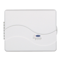
Each system controller is comprised of a three-zone controller and
a duct temperature sensor.
NOTE: Thermostats are purchased separately.
The comfort temperature settings can change automatically
through the use of schedules if programmable thermostats are
selected. This allows the Carrier 3-Zone to change the temperature
settings in zones to reflect occupancy or usage. The Carrier 3-Zone
system uses motorized air volume control dampers (also called
zone dampers) to regulate the flow of conditioned air into the
zones.
INSTALLATION
Step 1—Check Equipment and Job Site
INSPECT EQUIPMENT — File claim with shipping company,
prior to installation, if shipment is damaged or incomplete.
Visit www.carrier.com
Manufacturer reserves the right to discontinue, or change at any time, specifications or designs without notice and without incurring obligations.
Book 1144
Tab 3a 5a 2a 5a
PC 101 Catalog No. 809-50009 Printed in U.S.A. Form ZONEKIT-15SI Pg 1 11-04 Replaces: NEW