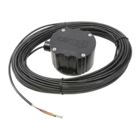
The CP-4 Automatic Gate Opener is a vehicle detection device designed to automatically open gates. It is compatible with all gate operators, whether powered or solar. The device is referred to as a "puck" due to its shape and is designed for both buried and above-ground installations.
Function Description:
The CP-4 operates by detecting vehicles, triggering the gate to open. It uses a sensing mechanism that can be adjusted for sensitivity. The device connects to the gate operator's control board via a wired connection, offering both dual and single exit terminal configurations.
Important Technical Specifications:
- Power Required: 8-24 VAC or 8-30 VDC
- Stand-By Current: 30-70 Microamps (µA)
- Alarm Current: 30-40 Milliamps (mA)
- Relay Time: 2-3 seconds
- Relay Contacts: SPDT, floating, N.O. or N.C. (Form C)
- Relay Contact Rating: 1 amp/24 VDC (1 mA at 5 VDC min. load)
- Enclosure Rating: IP67
- Strength Rating: 9.53 ton-force (8646 kgf)
- Temperature Range: -25° F. to +140° F. (-32° C. to +60° C.)
- Dimensions: 4.5 in. diameter x 2.5 in. high
- Weight: 5 lbs. with 100 ft. cable
- Warranty: 5-year warranty against defects in material and workmanship.
Usage Features:
Serial Number:
Each CP-4 unit has a barcode serial number located on the bottom of the "puck" and on the product box. This number is essential for product inquiries and support.
Connecting to Gate Operator:
The CP-4 offers flexible wiring options for gate operators:
- Dual Exit Terminal:
- RED: Power +
- BLACK: Power -
- WHITE: Common
- BLUE: Exit N.O.
- YELLOW: Exit N.C.
- Single Exit Terminal:
- RED: Power +
- BLACK: GND or COM
- BLUE: Free Exit or Open Terminal
Sensitivity Adjustment:
The device's sensitivity can be adjusted using dip switches, though in most cases, adjustment is not necessary.
- HIGH (Default): Detects vehicles going 5 MPH 12-14' away. Dip switches 1 & 2 are in the OFF position.
- MEDIUM: Detects vehicles going 5 MPH 6-8' away. Dip switch 1 is ON, and 2 is OFF.
- LOW: Detects vehicles going 5 MPH 2-3' away. Dip switches 1 & 2 are in the ON position.
- Note: The color of the dip switches may vary.
Installation Guidelines:
- Buried Installation:
- Trench 1/2" PVC pipe to the CP-4's placement.
- Smooth out the entire length of the cable before pulling it through the PVC pipe.
- Gently pull the cable through the PVC pipe (wire lubricant may be needed). The cable length is typically 80-100 feet, with a recommended 12-foot trench for the pipe.
- After pulling the cable through the plastic conduit, insert the conduit inside the slip joint on the "puck." Do NOT glue the slip joint to allow for un-installation if needed.
- Bury the conduit and "puck" 3-5 inches below the surface.
- Above-Ground Installation:
- The CP-4 can be installed above ground by screwing the "puck" directly to an immovable post or building.
- If installed above ground, use conduit to mechanically protect the cable from animals.
- Vehicle Speed: The car should be going at least 5 MPH at the sensor to be detected.
Placement Clearances:
To ensure optimal performance and avoid interference, install the CP-4 at least:
- 6-10 feet away from buried power, telephone, or invisible dog fences.
- 10 feet away from natural gas lines.
- 20 feet away from a power pole with a transformer.
- 100 feet back from railroad traffic.
- 200 feet away from high power substation power lines.
- 80-100 feet back from the gate operator.
Testing:
Test the unit with the gate by swinging steel over the puck (or driving a vehicle by). If it opens the gate correctly, proceed with burying the conduit and puck.
Maintenance Features:
Troubleshooting:
For troubleshooting, installers should call Cartell at (717) 532-0033, option 1.
Returning Merchandise (R.M.A.):
- Consumers: Contact your installer.
- Installers: Call Cartell at (717) 532-0033, option 1, to receive a Return Merchandise Authorization (R.M.A.) number. Write the R.M.A. number on the return shipping box and include any correspondence with the defective product.
- Distributors: Send installers directly to Cartell using (717) 532-0033, option 1.
Warranty Limitations:
The 5-year warranty does not cover defects caused by:
- Acts of God.
- Improper installation.
- Abuse.
- Fire damage.
- Electrical surges.
- Integrated system failures.
- Improper lid/gasket installation.
- Damage to cable (if applicable) caused by slicing, pulling, tangling, improper splicing, or not running in non-metallic conduit.
FCC Compliance:
The CP-4 complies with part 15 of the FCC Rules. Operation is subject to two conditions: (1) The device may not cause harmful interference, and (2) The device must accept any interference received, including interference that may cause undesired operation.
Chemical Warning:
This product can expose you to chemicals including Acrylonitrile, which is known to the State of California to cause cancer. For more information, go to www.P65Warnings.ca.gov.