INTRODUCTION
Congratulations on purchasing the most professional vehicle detection system available! It has been
manufactured in order to give years of trouble-free service. However, if it should need servicing, please
consult the dealer who installed your system.
Read these instructions completely. It is recommended that each system be bench-tested by the dealer
before installation as a standard practice. It is also recommended that the installer become acquainted with
the CT-2B control unit and sensor probe in the shop; make all adjustments and settings; and study all system
functions. If there are any questions or problems that need to be discussed, contact the Preferred’s technical
staff.
S
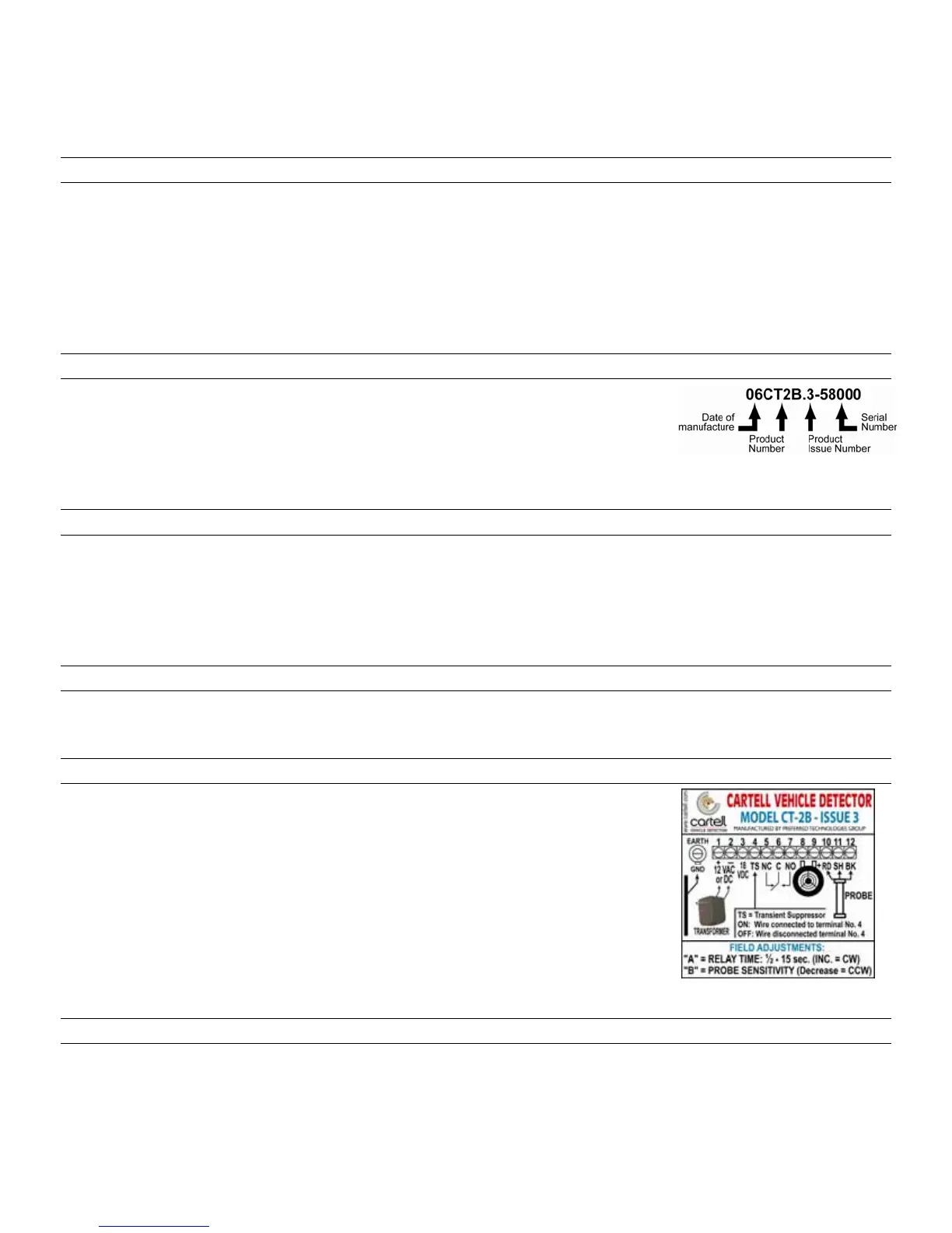
ERIAL NUMBER:
Attached to the circuit board relay is a sticker with a set of numbers and
letters. This series of numbers and letters reveal the specific unit, its year of
manufacture, its issue number and ends with the serial number (see
illustration).
When calling Preferred for technical help, please have these numbers handy so that your call may be
handled as intelligently and quickly as possible.
I
NSTALLING CONTROL UNIT
Install the control unit in a dry, weatherproof building away from heavy electrical motors, radio transmitters,
main power service, or any equipment that may introduce electrical or R. F. noise. Install control unit in a
sealed box when used in a corrosive atmosphere such as an animal barn or chemical plant.
For unheated buildings or other outdoor applications (such as gate operators), use the CT-2BG control unit,
as it is conformal coated and not susceptible to moisture caused by temperature changes. However, it should
still be installed in a sealed, weather-proof box or in the gate operator.
P
OWER AND BATTERY BACKUP
The control unit operates on 12 VAC or 12 VDC. Hook up the 12 VAC transformer as shown in Figure 1.
Built-in battery chargers do not come with this system. If battery backup is desired, any 12 VDC power pack
can be used. Hook up as shown for 12 VDC operation. Any 12 VDC power source may be used.
E
ARTH-GROUND
See Figure 1. Like all solid-state electronic systems, a proper earth-ground
is essential. A proper earth-ground is established by using an 8 foot copper
or copper-clad ground rod driven deeply into the earth. Note: DO NOT use a
galvanized ground rod.
Use a ground wire of at least 12 gauge. Solder it to the ground rod with a
torch and then clamp it to the ground rod. Before attaching the other end of
the ground wire to the control unit, tin the wire. Connect it to the left side of
the control board.
Special Note: If the grounding described above is not possible, it is better
not to ground the CT-2B circuit board. A poor ground can cause false
alarms.
T
RIP-TEST BUTTON
See Figure 1. The TRIP-TEST button, located center right on the circuit board, is a tool to evaluate most of
the control electronics and to help in setting the relay time.
Set the probe sensitivity potentiometer "B" to the halfway point (vertically). Push the trip-test button on and
1
Figure 1
Back to Table of Contents
Back to Table of Contents
Back to Table of Contents
Back to Table of Contents
Back to Table of Contents
Back to Table of Contents
CT-2B/CT-2BG CONTROL UNIT MANUAL
Note: the CT-2BG is the same as the CT-2B except the circuit board has been conformal coated
and therefore suitable for installation outdoors in a weather-proof box or gate operator.