CanvFR conpoREBlou MBBEL C-9 SERVICE RENUEL
Sm6
6.0 FtRTI0unL VFRHICAII0nl, cant.
6.3¥*:)¥:X::tb:::::#i{a#hedp*:I:°=L£=a=±±;#±rngFf:cgc;in
4 and IC4, pin 4 on the secpe's seecmd chamel. Cattpre the phase
angles betVArm secpe traes until a precise 360 degree phase shift is
chibited, first at IC5 and then I]C4. The phase shift netrorks are
tuned correctly if this 360 degree shift cocurs at a freqqucy betireen
8.OkHz and 8.8kHz on both channels and if hath chanels' phase shift
alig"nent frequencies track within 400 Hz of each other. The ncminal
frequency is 8.4kHz @ 360 degrees; 119 ndcrceeconds of signal delay.
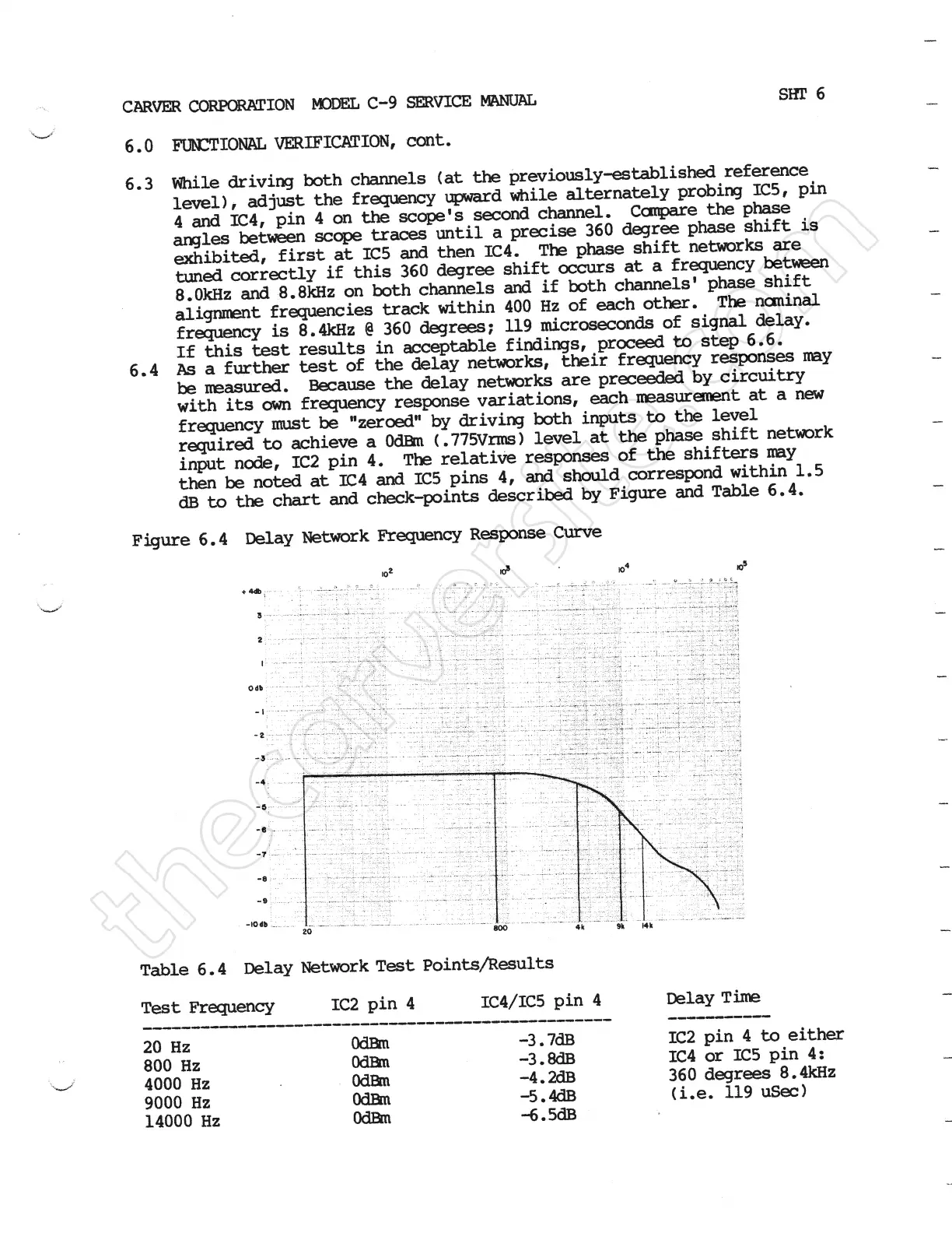
6.4::f:=ur=:I:E:=Fa:je:E===::y=::¥iF::ng:s=li::gT¥i:::e:,::n:*may
with its own frequeney response variaLtions, each measurerrmt at a new
freqLrmcy must be ''zeroed" ky driving both inputs to the lewel
required to achieve a Odrm { .775Vrms} 1ewel at the phase shift netcork
input nede, IC2 pin 4. The relative responses of the snifters my
then be noted at IC4 and IC5 pins 4, and shuld correspond within 1.5
dB to the chart and cheek-points descritrd by Figure and Tatle 6. 4.
Figure 6. 4 belay ifetrork Flequency Response Curve
Table 6. 4 belay ifetcork Test PointsAesults
Test Frequency IC2 pin 4 IC4/ICE pin 4
____--------------------------------------_-_
20Hz
800 Hz
4000 Hz
9000 Hz
14000 Hz
Odrm
Odrm
Odrm
OdEm
Odrm
-3 . 7dB
-3 . 8dB
-4 . an
-5 . 4dB
no . 5dE
belay Time
-----------
IC2 pin 4 to either
IC4 or EC5 pin 4:
360 degrees 8.4kHz
{i.e. 119 usee}
 Loading...